
User Manual

10. To use the bidirectional pass-through data lines such as those mentioned in the table below,
connect desired devices to the transmitter and receiver units.
11. Supply the extenders with 12 VDC power. If remote power is enabled on both sides (see
section on remote power below), the power adapter can be placed at either end. The other
unit will automatically receive power over the twisted pair cable connected between the
TPS ports. If remote power is disabled on either or both units, then both TX and RX must be
powered separately.
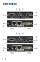
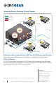
Ethernet
Use LAN cables to connect an Ethernet device (e.g. switch) to the Ethernet port on the Transmitter unit
and a network device (e.g. projector) to the Ethernet port on the Receiver unit - see warning on page 3.
RS-232
Use serial cables to connect a controller unit (e.g. touch panel) to the RS-232 port on the Transmitter unit,
and serial controlled device (e.g. projector) to the RS-232 port on the Receiver unit.
Infra-Red
Connect the supplied IR Transmitter to the IR OUT port of the transmitter unit.
Connect the supplied IR Receiver to the IR IN port on the Receiver unit.
Note 2: Never connect any third-party device to DVIGear devices while TPS remote power is enabled. The TPS
remote powering must only be used with TPS 95 Series extenders and MXP Series TPS I/O boards. Using it with other
devices may cause devices to be damaged.
Note 3: Table above contains examples of optional devices that are supported over the TPS twisted pair link. Note
that IR cannot be routed through the MXP Series Digital Matrix Routing Switchers.
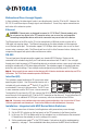
Remote Power Options
The TPS 95 Series TX and RX may either be powered separately
by power adapters or one device (TX or RX) may be used to power
the other remotely over the TPS link. Additionally, the units may
also be remotely powered by the MXP Series TPS I/O boards.
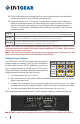
Remote powering can be enabled or disabled on the extenders by
conguring jumpers located on the sides of the units.
1. First, remove power from the TX and RX.
2. Next, remove the small access panel (shown removed below) on the sides of the units to reveal
the pins and jumper block.
3. To enable the remote power function, place the jumper block onto all the pins. The remote
powering feature must be congured on both TX and RX in order for this feature to be enabled.
4. To disable remote power, place the jumper block onto the upper line of pins only.
When remote powering is enabled on both TX and RX, the power adapter can be placed at either end.
Note 4: AWG 26 cables are not recommended with remote powering as they reduce maximum cable distances.
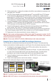
State
TX RX
Enabled
Disabled
(Default)
4