
User Manual

5. Set the remote power
(11)
modes on the extender units with the same method as is mentioned in the
stand-alone case - see page 4.
6. The TPS 95 Series extenders can be remotely powered
(11)
using the MXP Series TPS I/O boards
via the twisted pair cable that links the TPS In/Out ports. To achieve this, an optional external
power supply (p.n. DVI-MXP-PSU12V) must be connected to the 2-pin phoenix connector on each
TPS I/O board - see information below. If the remote power feature is disabled on the connected
TPS I/O board, then a local power adapter must be used to power the TPS extender unit.
7. Connect the extender(s) and the matrix board(s) using CAT-X
(11)(12)
cable(s). Connect the
transmitters’ TPS OUT connectors with the input boards’ TPS IN connectors and the receivers’
TPS IN connectors with the output boards’ TPS OUT connectors.
8. Connect the video source(s), sink(s) and the desired accessory device(s) to the MXP Series
matrix switcher. MXP Series TPS I/O boards do not support IR pass-through.
9. Next connect the video source(s), sink(s) and the desired accessory device(s) to the extenders.
10. Connect the power cord of the MXP Series switcher into an AC outlet and power ON the unit.
11. Supply power to the other connected units (sources, displays, etc.).
Note 11: Never connect any third-party device to DVIGear devices while TPS remote power is enabled. The TPS
remote powering must only be used with TPS 95 Series extenders and MXP Series TPS I/O boards. Using it with other
devices may cause devices to be damaged.
Note 12: For best results, CAT6A S/FTP (550 MHz) 23AWG twisted pair cable is highly recommended.
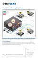
Remote Power Options with MXP Series Matrix Switchers
The TPS extenders can be powered remotely by the connected TPS I/O board. The remote powering
feature can be enabled or disabled separately on each I/O port of the matrix board using jumper settings.
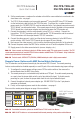
1. To congure the remote power settings, power OFF the matrix switcher, then remove the
desired boards from the MXP Series frame.
2. The remote power pins are located directly behind each TPS port. To enable remote powering
on a port, place the jumper block onto the set of pins behind that port. To disable remote
powering on a port, remove the jumper block from the set of pins behind that port.
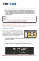
3. Connect the optional external power adapter (p.n. DVI-MXP-PSU12V) to the 2-pin phoenix
connector on the board.
4. Finally, set the required power mode for the extenders - see page 4.
Please see the remote power diagram on page 8 for more details.
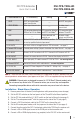
State
Boards Extenders
Enabled
Disabled
(Default)
Note 13: For detailed information, please see the MXP Series TPS I/O cards User Manual.
Note 14: AWG 26 CAT-X cables are not recommended with remote powering as they reduce cable distances.
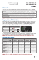
12VDC / 6.67A external
power adapter - ordered
separately.
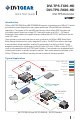
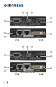
DVI-TPS-TX95-HD
DVI-TPS-RX95-HD
DVI TPS Extender
Quick Start Guide
7