949-1265:Layout 1 1/25/11 10:21 AM Page 1 Bulletin 949-1265 Instructions for the 16A2 & 16A3 Series Microprocessor Based Temperature / Process Control LOVE CONTROLS DIVISION DWYER INSTRUMENTS, INC. P.O. BOX 373 • MICHIGAN CITY, INDIANA 46360, U.S.A Phone: 219/879-8000 www.love-controls.com e-mail: love@love-controls.
949-1265:Layout 1 1/25/11 10:22 AM Page 2 CONTENTS GETTING STARTED . . . . . . . . . . . . . . . . . . . . . . . . . . . . . . . . . . . . . . . . . . . . . . .2 MODEL IDENTIFICATION . . . . . . . . . . . . . . . . . . . . . . . . . . . . . . . . . . . . . . . . . . .3 INSTALLATION . . . . . . . . . . . . . . . . . . . . . . . . . . . . . . . . . . . . . . . . . . . . . . . . . . .4 WIRING . . . . . . . . . . . . . . . . . . . . . . . . . . . . . . . . . . . . . . . . . . . . . . . . . . . . . . . . .
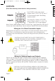
. .2 . .3 . .4 . .5 . .6 . .6 . .8 . .9 .1 0 .1 1 .1 1 .1 1 .1 2 .1 3 .15 .1 6 .1 6 .1 6 .1 7 .2 0 .2 0 .2 0 .2 8 .3 3 7-39 .4 0 .4 4 wire wiring rt on your cesthe ages 949-1265:Layout 1 1/25/11 10:22 AM Page 3 ENTER keys for 5 Seconds (see Page 28.) Press the INDEX key until the display shows 1nP and press the DOWN ARROW until the display shows P385. Don’t forget to press the ENTER key to retain your setting. Next, press the INDEX key to display Unit. Press the until the display shows C.
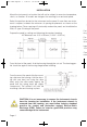
949-1265:Layout 1 1/25/11 10:22 AM Page 4 INSTALLATION Mount the instrument in a location that will not be subject to excessive temperature, shock, or vibration. All models are designed for mounting in an enclosed panel. Select the position desired for the instrument on the panel. If more than one instrument is required, maintain the minimum of spacing requirements as shown on the drawing below. Closer spacing will structurally weaken the panel, and invalidate the IP66, UL type 4X rating of the panel.
949-1265:Layout 1 1/25/11 10:22 AM Page 5 WIRING ture, strun the e the Do not run RTD, thermocouple, or other class 2 wiring in the same conduit as power leads. Use only the type of thermocouple or RTD probe for which the control has been programmed. Maintain separation between wiring of sensor, optional inputs and outputs and other wiring. See the “Secure Menu” for input selection. For thermocouple inputs always use extension leads of the same type designated for your thermocouple.
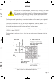
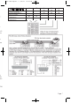
949-1265:Layout 1 1/25/11 10:22 AM Page 6 OUTPUTS O (Rear View showing center block of wiring terminals.) Output A Output B For AC SSR or relay type outputs (Output Codes 1 or 3), 15 & 16, and 17 & 18 are normally open. See Rating Label for details. For Pulsed DC, Current, or DC SSR ouputs (Output codes 2, 4, or 8), 15 & 17 are positive, 16 & 18 are negative. Note: Factory default assigns Output A to Set Point 1 and Output B to Set Point 2. If necessary, these realtionships may be reversed.
17 949-1265:Layout 1 1/25/11 OPTION/TERMINALS PV1 PV/SV Retransmission, Current (e.g. 4-20 mA) PV2 PV/SV Retransmission, Voltage (e.g. 0-10V) 992, 996 RS-485 Serial Communications 993, 995 RS-232 Serial Communications 10:22 AM 11 Page 7 12 6 7 8 + + B A na na na na na na na na na Data In Data Out Signal Ground na na & nt 2. nu.
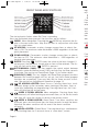
949-1265:Layout 1 1/25/11 10:22 AM Page 8 FRONT PANEL KEY FUNCTIONS The decimal point flashes when Self Tune is operating. Keys are illuminated when pressed. Key functions are as follows: INDEX: Menu Navigation. Pressing the INDEX key advances the display to the next menu item. May also be used in conjunction with other keys as noted below. UP ARROW: Increments a value, changes a menu item, or selects the item to ON. The maximum value obtainable is 9999 regardless of decimal point placement.
49-1265:Layout 1 1/25/11 10:22 AM Page 9 ing the control (similar to turning power off and on). ‘Global Reset’ will allow recovery from errors and reset the following menu items: AL i.H: Alarm inhibit 0PEn 1nP: Input error bA nP: Input err CHEC CAL: Check calibration Correct the problems associated with the above conditions before using the reset keys. More than one error could present. Caution is advised since several items are reset at one time.
949-1265:Layout 1 1/25/11 10:22 AM Page 10 PASSWORD TABLE Security Level Menu Status Primary Locked Secondary Locked Secure Locked Primary Unlocked Secondary Locked Secure Locked Primary Unlocked Secondary Unlocked Secure Locked Primary Unlocked Secondary Unlocked Secure Unlocked Displaying Value When Viewed Password Value To Enter 1 1110 The func pera Set V 1101 Item Run/ Desc 2 3 1011 4 111 NOTATION CONVENTIONS FOR THE MENUS Because of the number of features available in this control, inf
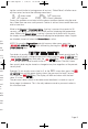
949-1265:Layout 1 1/25/11 10:22 AM Page 11 THE HOME DISPLAY To The home display is the normal display while the control is operating. If no errors or functions are active, the HOME display will indicate the Process Variable (the temperature, pressure, flow, RH, etc., that is being measured) on the top display and the Set Variable (Set Point 1) on the bottom.
949-1265:Layout 1 1/25/11 10:22 AM Page 12 to program the target set point and the time desired to reach that point. When the ramp segment is executed by the control, it calculates the ramp required to move the process from the starting value (current PV) to the desired value (programmed SP) in the time allowed. Set like temp set i Soaks (or dwells) are ramp segments where the target set point is the same as the beginning process value.
949-1265:Layout 1 1/25/11 10:22 AM Page 13 n the move med Set 1SP to the target value desired for the first ramp. This value is in actual units just like SP1. If the control is programmed for temperature, then the SP displays are in temperature. If the control is programmed for some other engineering unit, the SP is set in that unit. s the rmeeach ate a uiresired Press INDEX to continue. If Alarm 1 is programmed as an event (AL1 = EUnt), then 1A1 will appear.
949-1265:Layout 1 1/25/11 10:22 AM Page 14 Pressing the AUTO / MANUAL key will also suspend the program operation. The difference is that AUTO / MANUAL also puts the control into manual mode. See Auto / Manual operation on page 14. The function of the Primary Menu will change depending on the setting of the StAt menu item in the Secondary Menu. If StAt is 0FF then the Primary Menu is not changed.
tion. See menu rmamainn the nt in display, ress 949-1265:Layout 1 1/25/11 10:22 AM Page 15 AUTO / MANUAL OPERATION (16A3 ONLY) The AUTO / MANUAL function allows you to manually adjust the output of the control. This is normally used during process setup or start up. It can also be used for troubleshooting. To switch from AUTO to MANUAL press the AUTO / MANUAL key and hold for three seconds.
949-1265:Layout 1 1/25/11 10:22 AM Page 16 Operating of Self Tune Function Self Tune allows automatic selection of the necessary parameters to achieve best control operation from your 16A2 & 16A3 Series control. If you are using the control output as a simple on-off function (0ut 1 set for 0n0F), none of the following will apply.
949-1265:Layout 1 1/25/11 10:22 AM Page 17 OPERATION AND PROGRAMMING OF OPTIONS est onng Pid dary conand value asts ffect ting. alcuchols conrivaampls. A dary o the Tune n the Option 992, 993, 995, 996 Serial Communication The serial communications options allow the control to be written to and read from a remote computer or other similar digital device. Communication is allowed either through a RS-485 (Option 992, 996) port, or a RS-232 (Option 993, 995) port.
949-1265:Layout 1 1/25/11 10:22 AM Page 18 Serial Communications Options and Non-volitile Memory There are many different types of memory used in computer driven devices. The terms RAM (random access memory) and ROM (read only memory) are a couple with which you may be familiar. If yo ming to us RAM is used in computers to run programs and hold data for a short period of time. This is the memory that is used primarily in PCs. RAM is very fast and can be read and written to over and over again.
949-1265:Layout 1 1/25/11 10:22 AM Page 19 The uple If you think about how long it would take a million changes to the control programming through the front key pad, you will see that it would take a very long time to get to use up the life of the EEPROM. ime. read Adding one of the computer communications options (e.g. 992, 993) changes the picture. The speed of computer communications is such that hundreds of instructions can be made in less than a minute.
949-1265:Layout 1 1/25/11 10:23 AM Page 20 MENU SELECTIONS PRIMARY MENU Press INDEX to advance to the next menu item. Press UP ARROW or DOWN ARROW to change the value in the display. Press ENTER to retain the value. If StAt, (Secondary Menu [16A3]), is 0n, the three program status menu items shown on Page 14 will precede the folowing. SP1 Set Point 1 Adjust, Control Point 1. SP2 Set Point 2 Adjust (if equipped), Control Point 2. SECONDARY MENU Hold UP ARROW & ENTER.
949-1265:Layout 1 0ut1 1/25/11 10:23 AM Output selection: Select 0n0F W or R to atus 0n0F, #tP, #PuL, or ProP. A setting of 0n0F allows the control to operate in simple on/off mode. This setting forces the control to turn off at set point, and on at the set point plus the differential (SP1d). When selected, the 0ut1 0n0F menu items is followed by #### SP 0d, and the tunE, Pb, rES, 510L and 510H selections in the Secure menu are suppressed.
949-1265:Layout 1 1/25/11 10:23 AM Page 22 The following menu items apply only if your control is equipped with a second set point (last digit of model number is not zero). If your control does not have a second set point, jump to the tunE menu on the next page. 0ut2 Output selection: Select OnOF, #tP, #PuL, or ProP. 0n0F A setting of 0n0F allows the control to operate in simple on/off mode. This setting forces the control to turn off at set point, and on at the set point plus the differential (SP2d).
seces 949-1265:Layout 1 g L. 10:23 AM Page 23 SP (Option 948, 4-Stage Set Point) Active Set Point Stage. Select 1SP1, 25P1, 35P1, 45P1. (See Page 17 for more detail.) 1SP1 Set Menu Items to display Stage 1 for view and change access. If SPSA is set for 1nt, 1SP1 is made active. 25P1 Set Menu Items to display Stage 2 for view and change access. If SPSA is set for Int, 25P1 is made active. 35P1 Set Menu Items to display Stage 3 for view and change access. If SPSA is set for Int, 35P1 is made active.
949-1265:Layout 1 1/25/11 10:23 AM Page 24 rES SL0 nor FASt Pid2 ArUP ArtE Fint Fbnd Automatic Reset Time. Select 0FF, 0.1 to 99.9 minutes. Select 0FF to switch to 0FS. 0FS Manual Offset correction Select. Select 0FF, 0.1 to 99.9 percent. Select 0FF to switch to rES. rtE Rate Time. Select 0FF, 0.1 to 99.9 minutes. Derivative. PID values are preset for a slow response process. PID values are preset for a normal response process. PID values are preset for a fast response process.
949-1265:Layout 1 es. 1/25/11 10:23 AM Page 25 FrtE Fuzzy Logic Rate of Change: Select 0.00 to 99.99 counts/second. For best initial setting, find the counts/second change of process value near Set Point 1 with output ON 100%. Multiply this value by 3. Set FrtE to this calculated value. PEA The Peak feature stores the highest input the control has measured since the last reset or Power On. At Power On PEA is reset to the present input. To manually reset the value PEA must be in the lower display.
949-1265:Layout 1 tbAS 1/25/11 10:23 AM Page 26 Ramp/Soak Time Base (16A3): Select 1_S or 60_S. 1_S Ramp/Soak time base is in 1 second increments. Program time 1ti ...16ti is measured in seconds. 60_S Ramp/Soak time base is in 60 second increments (minutes). Program time 1ti ...16ti is measured in minutes. The following items repeat in the following order: 1ti ,1SP,1A1 (if AL1 is programmed as EUnt), 2ti , 2SP, 2A1, . . . , 16ti, 16SP, 16A1. To avoid repetition each item will only be described once.
949-1265:Layout 1 10:23 AM Page 27 LPbr Loop Break Protection: Select 0FF, 1 to 9999 seconds. If, during operation, the output is minimum (0%) or maximum (100%), and the input moves less than 5°F (3°C) or 5 counts over the time set for LPbr, the L00P bAd message will appear. This condition can also be routed to an Alarm Condition if alarms are present and turned On (see ALbr in the Secure Menu). The loop break error can be reset by pressing the ENTER key when at the LPbr menu item.
949-1265:Layout 1 Unit ch enu. nce nge F, C or F C nonE 1/25/11 10:23 AM Page 29 nonE. °F descriptor is On and temperature inputs will be displayed in actual degrees Fahrenheit. °C descriptor is On and temperature inputs will be displayed in actual degrees Celsius. °F and °C descriptors will be Off. This is only available with Current and Voltage Inputs. dPt Decimal Point Positioning: Select 0, 0.0, 0.00, 0.000, or .0000.
949-1265:Layout 1 1/25/11 10:23 AM Page 30 APCt Manual and PctO display adjustment (16A3). Select rEAL or AdJ. rEAL Manual display will display output 0 to 100% relative to actual range of the output. AdJ Manual display will display output 0 to 100% relative to the S#0L and S#0H settings. S1S SEnC Sensor Rate of Change: Select 0FF, 1 to 4000 °F, °C, or counts per 1 second period.
ctual e stest or at d ction an et. ng l set ges. ng l set ges. This s for This s for d) is d) is 949-1265:Layout 1 1/25/11 10:23 AM Page 31 S1St Set Point 1 state : Select dir or rE. dir Direct Action. As the input increases the output will increase. Most commonly used in cooling processes. rE Reverse Action. As the input increases the output will decrease. Most commonly used in heating processes. If 0ut1 (Page 21) is set for ##tP, #PUL, or ProP, then S10L and S10L appear.
949-1265:Layout 1 1/25/11 10:23 AM Page 32 S1Pi Set Point 1 Power Interrupt. Select 0n or 0FF. 0n Alarm Power Interrupt is 0n. Output will automatically reset on power-up if no alarm condition exists. 0FF Alarm Power Interrupt is 0FF. Output will be in the alarm condition on power-up regardless of condition of process. S1iH Set Point 1 Inhibit: Select 0n or 0FF. 0n Alarm Inhibit is On. Alarm action is suspended until the process value first enters a non-alarm condition. 0FF Alarm Inhibit is OFF.
949-1265:Layout 1 1/25/11 10:23 AM Page 33 force a full on condition for output devices which do not have bias adjustments. Factory set to 100 for all output codes. If 0ut2 is set to 0n0F (in the Secondary Menu), then the next three menu items can make the SP2 and SP2d settings act like a high or low alarm set point. See the information on alarm settings and the cautions and warnings that apply to them on the next pages.
949-1265:Layout 1 1/25/11 10:23 AM Page 34 example if a low alarm isrequired to be 5 degrees below the Set Point, then set A1Lo to -5. If a high alarm is required 20 degrees above the Set Point, then set A1Hi to +20. If the Set Point is changed, the alarm will continue to hold the same relationship as originally set. The AL1 The diagram below shows the action and reset functions for both absolute and deviation alarms.
t me 949-1265:Layout 1 1/25/11 10:23 AM Page 35 The following menu items apply only to the alarm. AL1 Alarm 1 function: Select 0FF, Lo, Hi, HiLo, or EUnt. 0FF Alarm 1 is disabled. No Alarm 1 menu items appear in the Secondary or Secure menus. Lo Low Alarm Only. A1Lo appears in the Secondary Menu. Hi High Alarm Only. A1Hi appears in the Secondary Menu. HiLo High and Low Alarms. Both A1Lo and A1Hi appear in the Secondary Menu, and share the same Alarm 1 Relay output.
949-1265:Layout 1 1/25/11 10:23 AM Page 36 A1LP Alarm 1 Lamp: Select 0on or 0oFF. 0on Alarm Lamp is ON when alarm contact is closed. 0oFF Alarm Lamp is OFF when alarm contact is closed. A1Lb Alarm 1 Loop Break. Select 0n or 0FF. 0n Loop Break Condition will cause an Alarm Condition. 0FF Loop Break will not affect the Alarm Condition. Addr (Option 992, 993, 995, 996, Serial Communications) Control Address: Set from 1 to 3FF for Options 992 and 993. Set from 1 to FF for options 993 and 995.
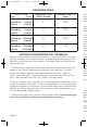
949-1265:Layout 1 1/25/11 10:23 AM Page 37 Set 993 s ed off Baud 0 atch e unts ERROR MESSAGES Any error message may be cleared by using the ‘Global Reset’ by pressing and holding the INDEX & ENTER keys for five seconds. : s are s are DISPLAY MEANING SP OUTPUTS ACTION REQUIRED This message Set point out- Correct the ambient temperaArEA appears if the puts ture (Alternates ambient temperaactive. conditions. Ventilate the with PV) ture of the control Alarm active.
949-1265:Layout 1 1/25/11 10:23 AM Page 38 ERROR MESSAGES Any error message may be cleared by using the ‘Global Reset’ by pressing and holding the INDEX & ENTER keys for fi ve seconds. DISPLAY UFL or 0FL bAd 1nP 0PEn 1nP L00P bAd SEnC bAd A MEANING SP OUTPUTS ACTION REQUIRED DIS Underflow or Overflow: Process value has exceeded input range ends. Set point outputs active. Alarm active. May be normal if Input signals go above or below range ends.
949-1265:Layout 1 1/25/11 10:23 AM Page 39 ERROR MESSAGES Any error message may be cleared by using the ‘Global Reset’ by pressing and holding the INDEX & ENTER keys for fi ve seconds. D nals nds. sor, DISPLAY MEANING SP OUTPUTS ACTION REQUIRED Display is blank. Set point outputs inactive. Alarm inactive Check that the power supply is on, measure supply voltage, check that the external fuses are good. Set point outputs inactive.
949-1265:Layout 1 1/25/11 10:23 AM Page 40 SPECIFICATIONS Selectable Inputs: Thermocouple, RTD, DC Voltage, or DC Current selectable. Input Impedance: Thermocouple = 3 megohms minimum. RTD current = 200 µA. Current = 10 ohms. Voltage = 5000 ohms. Sensor Break Protection: De-energizes control output to protect system after customer set time. (See InPt in Secure Menu.) Set Point Range: Selectable (See Input Ranges Page 43). Display: Two 4 digit, 7 segment 0.3” high LEDs.
949-1265:Layout 1 1/25/11 10:23 AM Page 41 Humidity Conditions: 0 to 90% up to 40°C non-condensing, 10 to 50% at 55°C non-condensing. Memory Backup: Nonvolatile memory. No batteries required. Control Output Ratings: SSR: 2.0 A combined outputs A & B @ 240 VAC at 25°C (77°F). Derates to 1.0 A @ 55°C (130°F). Relay: SPST, 3 A @ 240 VAC resistive; 1.5A @ 240 VAC inductive; Pilot duty rating 240 VA, 2 A @ 120 VAC or 1 A 240 VAC. Alarm Relay: SPST, 3 A @ 240 VAC resistive; 1/10 HP @ 120 VAC.
949-1265:Layout 1 -992 -993 -995 -996 1/25/11 10:23 AM Page 42 RS-485 Series Communications Port Compliance: EIA-485. Isolation: 500 VAC. Protocol: Lovelinks™ II. Address Range: 001H or 3FFH. Baud Rates: 300, 1200, 2400, 4800, 9600, Mode: Half duplex. Character: 8 bits, 1 start, 1 stop, no parity. Number of units on line/ports1: 32. Cable Lengths1: 6,000 ft (1,828 m). Termination: 120 Ohms, balanced. RS-232 Series Communications Port Compliance: RS-232C. Isolation: 500 VAC. Protocol: Lovelinks™ II.
949-1265:Layout 1 1/25/11 10:23 AM Page 43 Termination: 120 Ohms, balanced. 1 Number can be increased through use of a repeater such as the Mother Node™. Consult factory for details.
949-1265:Layout 1 1/25/11 10:23 AM ©Copyright 2012 Dwyer Instruments, Inc. Page 44 Printed in U.S.A. 1/12 LOVE CONTROLS DIVISION DWYER INSTRUMENTS, INC. P.O. BOX 373 • MICHIGAN CITY, INDIANA 46360, U.S.A FR# 949-1265 Rev. 9 Phone: 219/879-8000 www.love-controls.com e-mail: love@love-controls.