
Manual


Page 4
INSTALLATION
Mount the instrument in a location that will not be subject to excessive temperature,
shock, or vibration. All models are designed for mounting in an enclosed panel.
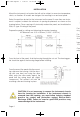
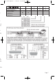
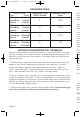
Select the position desired for the instrument on the panel. If more than one instru-
ment is required, maintain the minimum of spacing requirements as shown on the
drawing below. Closer spacing will structurally weaken the panel, and invalidate the
IP66, UL type 4X rating of the panel.
Prepare the panel by cutting and deburring the required opening.
All Tolerances are -0.00 +0.60mm (-0.000 + 0.020 in.)
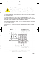
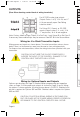
From the front of the panel, slide the housing through the cut out. The housing gas-
ket should be against the housing flange before installing.
From the rear of the panel slide the mount-
ing collar over the housing. Hold the hous-
ing with one hand and using the other
hand, push the collar evenly against the
panel until the spring loops are slightly
compressed. The ratchets will hold the
mounting collar and housing in place.
CAUTION: It is not necessary to remove the instrument chassis
from the housing for installation. If the instrument chassis is
removed from the housing, you must follow industry standard
practice for control and protection against Electro-Static
Discharge (ESD). Failure to exercise good ESD practices may
cause damage to the instrument.
For t
for y
For s
Use
disco
Inpu
15 V
Con
mina
949-1265:Layout 1 1/25/11 10:22 AM Page 4