
Manual


Page 5
ture,
stru-
n the
e the
gas-
ssis
s is
dard
atic
may
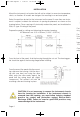
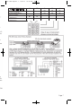
For thermocouple inputs always use extension leads of the same type designated
for your thermocouple.
For supply connections use No. 16 AWG or larger wires rated for at least 75°C.
Use copper conductors only. All line voltage output circuits must hvave a common
disconnect and be connected to the same pole of the connect.
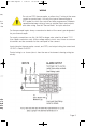
Input wiring for thermocouple, current, and RTD; and output wiring for current and
15 VDC is rated CLASS 2.
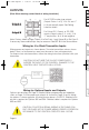
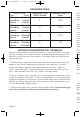
Control wiring is as shown (view is from the rear of instrument showing wiring ter-
minals).
Do not run RTD, thermocouple, or other class 2 wiring in the same
conduit as power leads. Use only the type of thermocouple or
RTD probe for which the control has been programmed. Maintain
separation between wiring of sensor, optional inputs and outputs
and other wiring. See the “Secure Menu” for input selection.
WIRING
949-1265:Layout 1 1/25/11 10:22 AM Page 5