
Manual


949-1270 Page 2 of 28 December, 1998
CONTENTS
MODEL IDENTIFICATION...................................................................... 2
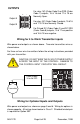
GETTING STARTED............................................................................... 3
INSTALLATION....................................................................................... 4
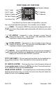
WIRING................................................................................................... 5
Wiring for 4 to 20mA Transmitter inputs ........................................... 6
Wiring for Optional Inputs and Outputs ............................................. 6
FRONT PANEL KEY FUNCTIONS ......................................................... 8
NOTATION CONVENTIONS FOR THE MENUS ................................. 10
THE HOME DISPLAY ........................................................................... 11
OPERATION AND PROGRAMMING OF OPTIONS ............................ 11
MENU SELECTIONS ........................................................................... 14
PRIMARY MENU .................................................................................. 14
SECONDARY MENU ............................................................................ 14
SECURE MENU.................................................................................... 17
DIAGNOSTIC ERROR MESSAGES..................................................... 22
SPECIFICATIONS ................................................................................ 24
DIMENSIONS ....................................................................................... 27
© 1998, Love Controls Division, Dwyer Instruments, Incorporated. All rights reserved. No
portion may be copied without the express written consent of Love Controls.
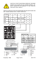
MODEL IDENTIFICATION
Model 1 6 L 2 0 — —
Output 1
1 = SSR
2 = 15 VDC
3 = Relay, NO
4 = Relay, NC
8 = DC SSR
Output 2
0 = None
1 = SSR
2 = 15 VDC
3 = Relay, NO
4 = Relay, NC
8 = DC SSR
OPTIONS
Options:
934 Analog Retransmission of Process Variable, 4 to 20 mAdc.
936 Analog Retransmission of Process Variable, 0 to 10 Vdc.
948 4-Stage Set Point.
992 RS-485 Serial Communications.
993 RS-232 Serial Communications.
9502 12 - 24 Vdc/Vac 50-400Hz power supply (control operates on low
voltage equipment).
Note: Only Option 9502 may be combined with another option.