
Manual


December, 1998 Page 5 of 28 949-1270
WIRING
Do not run thermocouple or other class 2 wiring in the same conduit as
power leads. Use only the type of thermocouple or RTD probe for which
the control has been programmed. Maintain separation between wiring of
sensor, auxiliary in or out, and other wiring. See the "Secure Menu" for input
selection.
For thermocouple input always use extension leads of the same type
designated for your thermocouple.
For supply connections use No. 16 AWG or larger wires rated for at least
75°C. Use copper conductors only. All line voltage output circuits must
have a common disconnect and be connected to the same pole of the
disconnect.
Input wiring for thermocouple, current, and RTD; limit reset function; and
output wiring for 15 VDC is rated CLASS 2.
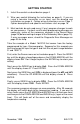
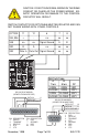
Control wiring is as shown.
Current
RTD*
Voltage
Thermocouple
+
-
+
-
* For 2-wire RTD use terminals 1 & 3, and
place a jumper wire between terminals 3 & 4.
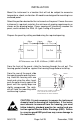
F1
3/8 A @250 VAC
Medium Lag
INPUTS
Line Input See Rating
Label for details
ALARM
RESET
+
-
An external
normally open
contact may
be wired
across
terminals 9 &
10 for remote
reset.
Multiple units
can not share
common
contacts.
Terminals 9 &
10 share a
common
ground with
the input.