
Manual


949-1270 Page 6 of 28 December, 1998
Wiring for Optional Inputs and Outputs
Wire power and outputs as shown on page 5 and 6. Wiring for options is
shown opposite. All wiring shown below is Class 2. Shielded twisted pair
is required for Option 992.
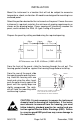
Wiring for 4 to 20mA Transmitter inputs
Wire power and outputs as shown above. Two-wire transmitters wire as
shown below.
For three or four wire transmitters follow the wiring instructions provided
with your transmitter.
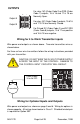
CAUTION: DO NOT WIRE THE 24 VOLT POWER SUPPLY
ACROSS THE INPUT OF THE CONTROL. DAMAGE TO
THE CONTROL INPUT CIRCUITRY WILL RESULT.
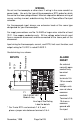
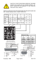
OUTPUTS
Output A
Output B
+ -
+ -
Power Supply
15 to 28 VDC
+
-
Transmitter
+
-
-
+
For relay, NO (Order Code 3) or SSR (Order
Code 1) outputs, 15 & 16 and 17 & 18 are
Normally Open.
For relay, NC (Order Code 4) outputs, 15 & 16
and 17 & 18 are Normally Closed.
For Pulsed DC (Order Code 2) and DC SSR
(Order Code 8) outputs, 15 & 17 are positive
and 16 & 18 are negative.