
Product Overview
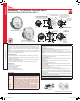

MAGNEHELIC
®
DIFFERENTIAL PRESSURE GAGES
Indicate Positive, Negative or Differential, Accurate within 1%
21
Differential Pressure Gages
PRESSURE
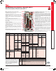
Bezel provides ange for ush mounting in panel.
Clear plastic face is highly resistant to breakage. Provides
undistorted viewing of pointer and scale.
Precision litho-printed scale is accurate and easy to read.
Calibrated range spring is at spring steel. Small
amplitude of motion assures consistency and long life. It
reacts to pressure on diaphragm. Live length adjustable for
calibration.
Red tipped pointer of heat treated aluminum tubing is easy
to see. It is rigidly mounted on the helix shaft.
Pointer stops of molded rubber prevent pointer over-travel
without damage.
“Wishbone” assembly provides mounting for helix, helix
bearings and pointer shaft.
Jeweled bearings are shock-resistant mounted; provide
virtually friction-free motion for helix. Motion damped with
high viscosity silicone uid.
Helix is precision made from an alloy of high magnetic
permeability. Mounted in jeweled bearings, it turns freely,
following the magnetic eld to move the pointer across the
scale.
Zero adjustment screw is conveniently located in the
plastic cover, and is accessible without removing cover.
O-ring seal provides pressure tightness.
O-ring seal for cover assures pressure integrity of case.
OVERPRESSURE PROTECTION
Blowout plug is comprised of a rubber plug on the rear
which functions as a relief valve by unseating and venting
the gage interior when over pressure reaches approximately
25 psig (1.7 bar). To provide a free path for pressure relief,
there are four spacer pads which maintain 0.023˝ clearance
when gage is surface mounted. Do not obstruct the gap
created by these pads.
The blowout plug is not used on models above 180˝ of
water pressure, medium or high pressure models, or on
gages which require an elastomer other than silicone for the
diaphragm.
The blowout plug should not be used as a system
overpressure control. High supply pressures may still
cause the gage to fail due to over pressurization, resulting
in property damage or serious injury. Good engineering
practices should be utilized to prevent your system from
exceeding the ratings of any component.
Die cast aluminum case is precision made and iridite-
dipped to withstand 168 hour salt spray corrosion test.
Exterior nished in baked dark gray hammerloid. One case
size is used for all standard pressure options, and for both
surface and ush mounting.
Silicone rubber diaphragm with integrally molded O-ring
is supported by front and rear plates. It is locked and
sealed in position with a sealing plate and retaining ring.
Diaphragm motion is restricted to prevent damage due to
overpressures.
Samarium Cobalt magnet mounted at one end of range
spring rotates helix without mechanical linkages.
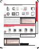
VELOCITY AND VOLUMETRIC FLOW UNITS
Scales are available on the Magnehelic
®
gage that read in velocity units (FPM, m/s)
or volumetric ow units (SCFM, m
3
/s, m
3
/h).
Stocked velocity units with dual range scales
in inches w.c. and feet per minute are shown
above. For other ranges contact the factory.
When ordering volumetric ow scales please
specify the maximum ow rate and its
corresponding pressure.
Example: 0.5 in w.c. = 16,000 CFM.
A-310A
SERIES 2000
DWYER INSTRUMENTS, INC. | dwyer-inst.com
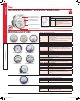
ACCESSORIES
Model Description
A-321
A-448
A-135
A-401
A-310A
Safety relief valve
3-piece magnet kit for mounting Magnehelic
®
gage directly to magnetic surface
Rubber gasket for panel mounting
Plastic carry case
3-way vent valves. In applications where pressure is continuous and the Magnehelic
®
gage
is connected by metal or plastic tubing which cannot be easily removed, we suggest using
Dwyer A-310A vent valves to connect gage. Pressure can then be removed to check or
re-zero the gage
MODEL CHART
Model
Range,
Inches of Water Model
Range,
PSI Model
Range, MM
of Water Model
Range,
kPa
Dual Scale Air Velocity Units
For use with pitot tube
2000-00N†••
2000-00†••
2000-0†•
2001
2002
2003
2004
2005
2006
2008
2010
2012
2015
2020
2025
2030
2040
2050
2060
2080
2100
2120
2150
2160
2180*
2250*
.05-0-.2
0-.25
0-.50
0-1.0
0-2.0
0-3.0
0-4.0
0-5.0
0-6.0
0-8.0
0-10
0-12
0-15
0-20
0-25
0-30
0-40
0-50
0-60
0-80
0-100
0-120
0-150
0-160
0-180
0-250
2201
2202
2203
2204
2205
2210*
2215*
2220*
2230**
0-1
0-2
0-3
0-4
0-5
0-10
0-15
0-20
0-30
2000-6MM†••
2000-10MM†•
2000-15MM
2000-25MM
2000-30MM
2000-50MM
2000-80MM
2000-100MM
2000-125MM
2000-150MM
2000-200MM
2000-250MM
2000-300MM
0-6
0-10
0-15
0-25
0-30
0-50
0-80
0-100
0-125
0-150
0-200
0-250
0-300
2000-0.5KPA
2000-1KPA
2000-1.5KPA
2000-2KPA
2000-2.5KPA
2000-3KPA
2000-4KPA
2000-5KPA
2000-8KPA
2000-10KPA
2000-15KPA
2000-20KPA
2000-25KPA
2000-30KPA
0-0.5
0-1
0-1.5
0-2
0-2.5
0-3
0-4
0-5
0-8
0-10
0-15
0-20
0-25
0-30
Model
Range, in w.c./
Velocity F.P.M.
2000-00AV†••
2000-0AV†•
2001AV
2002AV
2005AV
2010AV
0-.25/
300-2000
0-.50/
500-2800
0-1.0/
500-4000
0-2.0/
1000-5600
0-5.0/
2000-8800
0-10/
2000-12500
Model
Range, CM
of Water
2000-15CM
2000-20CM
2000-25CM
2000-50CM
2000-80CM
2000-100CM
2000-150CM
2000-200CM
2000-250CM
2000-300CM
0-15
0-20
0-25
0-50
0-80
0-100
0-150
0-200
0-250
0-300
Zero Center Ranges
2300-6MM†••
2300-10MM†•
2300-20MM†•
3-0-3
5-0-5
10-0-10
Zero Center Ranges
2300-1KPA
2300-2KPA
2300-2.5KPA
2300-3KPA
.5-0-.5
1-0-1
1.25-0-1.25
1.5-0-1.5
Model Range, Pa
2000-60NPA†••
2000-30PA†••
2000-60PA†••
2000-100PA†•
2000-125PA†•
2000-250PA
2000-300PA
2000-500PA
2000-750PA
2000-1000PA
10-0-50
0-30
0-60
0-100
0-125
0-250
0-300
0-500
0-750
0-1000
Dual Scale English/Metric Models
Model
Range,
in w.c.
Range,
Pa or kPa
Zero Center Ranges
2000-00D†••
2000-0D†•
2001D
2002D
2003D
2004D
2005D
2006D
2008D
2010D
2015D
2020D
2025D
2050D
2060D
0-.25
0-0.5
0-1.0
0-2.0
0-3.0
0-4.0
0-5.0
0-6.0
0-8.0
0-10
0-15
0-20
0-25
0-50
0-60
0-62 Pa
0-125 Pa
0-250 Pa
0-500 Pa
0-750 Pa
0-1.0 kPa
0-1.25 kPa
0-1.5 kPa
0-2.0 kPa
0-2.5 kPa
0-3.7 kPa
0-5 kPa
0-6.2 kPa
0-12.4 kPa
0-15 kPa
2300-4CM
2300-10CM
2300-30CM
2-0-2
5-0-5
15-0-15
Zero Center Ranges
2300-00†••
2300-0†•
2301
2302
2304
2310
2320
2330
0.125-0-0.125
.25-0-.25
.5-0-.5
1-0-1
2-0-2
5-0-5
10-0-10
15-0-15
Zero Center Ranges
Model Range, Pa
2300-60PA†••
2300-100PA†•
2300-120PA
2300-200PA
2300-250PA
2300-300PA
2300-500PA
2300-1000PA
30-0-30
50-0-50
60-0-60
100-0-100
125-0-125
150-0-150
250-0-250
500-0-500
†These ranges calibrated for vertical scale position • Accuracy ±3% •• Accuracy ±4% *MP option standard **HP option standard
YEAR LIMITED
WARRANTY
Pressure_2021.indb 21 7/15/20 8:10 AM