
Owner's manual


INSTALLATION
Pre-installation Requirements
Environment: Suitable for installation in intrinsically safe operation in
hazardous locations outdoors (NEMA 4X, CSA.ENC.4 & IP65).
Electrical Input: 4-20 mA DC current source.
Air Supply: Clean, dry, oil free instrument air filtered to 40 micron.
Mounting
The standard mounting kit enables panel or wall mounting of the unit.
For 1-1/2˝ and 2˝ pipe mounting, use the optional kit that is Dwyer
Instruments, Inc. part number A-182.
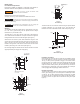
To mount unit to a 1-1/2˝ pipe, use two 10-32 holes on the back of the
unit to attach bracket to transducer. then place U-bolt around pipe and
through bracket. Place nuts on U-bolt and tighten (see Figure 1).
With access to the rear of a panel, attach transducer using two 10-32
screws and the two threaded mounting screws on the back of the unit.
With no access to the back of the panel, attach the bracket to the
transducer using the two 10-32 holes on the back of the unit and mount
bracket to panel using four 10-32 screws (see Figure 2).
Due to its light weight, the Series 2700 can also be mounted in line with
support provided by the supply and output piping.
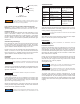
The Series 2700 can be mounted to a DIN-rail using the optional kit that
is Dwyer Instruments, Inc. part number A-181. This will allow the
transducer to mount to DIN 50045, 50035, 50022 rails (see Figure 3).
Pneumatic Connections
Clean all pipe lines to remove dirt and scale prior to installation. Supply
air must be filtered to 40 microns and free of moisture and lubricants.
Two (2) 1/4˝ NPT ports are provided for supply air connections. Either
port may be used. The unused port must be plugged with the pipe plug
included with the unit. Two (2) 1/4˝ ports are provided for pneumatic
output connections. Either port may be used and one may be used for
the mounting of an output gage. If no gage is installed, the unused port
must be plugged with the pipe plug included with the unit.
Electrical Connections
The Series 2700 is a two wire device (does not require a separate power
source), plus a safety ground. The unit requires a variable input current
of 4-20 mA. The 1/2˝ NPT conduit connection is made using 18˝ pigtail
wire coming from the unit. Electrical connections are made to the red (+)
and black (-) leads. The green lead is furnished for case ground (see
Figure 4).
Figure 1
Pipe Mounting
22 GA. WIRE LEADS
APPROX. 18˝ LONG
POS, NEG, GRD
2-15/16
(74.7)
5/16
(7.92)
3-11/16
(93.7)
2-3/16
(55.4)
PIPE CLAMP MOUNTING OPTION
FOR 1-1/2 PIPE
1
(25.4)
1/2
(12.7)
1/8
(
3.17)
1
-1/2
(38.1)
1
-19/64
(33.0)
1-51/64
(45.7)
MOUNTING HOLES
#
10-32 UNF-2B x 3/8 DP
2 PLCS
3
9/64
(
15.5)
1-11/16
(42.7)
DIN RAIL MOUNTING
OPTION
3-23/64
(85.3)
2-1/4
(57.2)
1-1/8
(28.7)
1/2 NPT
IN & OUT PORTS
1/4-18 NPT
4 PLCS
49/64
(19.4)
25/64
(9.72)
33/64
(13.1)
3-1/8
(79.2)
1-1/2
(38.1)
F
igure 2
P
anel Mounting
Figure 3
DIN Rail Mounting Kit
Clean all pipe lines to remove dirt and scale prior to installation.
Failures attributable to instrument air supply contamination are
not covered by the warranty.
N
OTICE
This instrument vents to atmosphere. The use of supply gas
other than air can create a hazardous environment.
CAUTION
A
ll wiring must be made to all local and national codes
a
ppropriate to the area of installation.
WARNING