
Owner's manual

Factory Mutual Research Corporation (FM) Intrinsically Safe
Ratings: IS / I, II, IIII / 1 / CDEFG / T4 Ta = 70°C - 431-990-036; Entity;
Type 4X Entity Parameters: Vmax = 30 V, Imax = 0.7 W, Ci = 0, Li = 0
Equipment Ratings:
Intrinsically safe electrical apparatus with Entity parameters for use in
Class I, II, III, Division 1, Groups C, D, E, F and G in accordance with
manufacturing Control Drawing No. 431-990-036, Rev. 1; nonincendive
for Class I, Division 2, Groups A, B, C and D; suitable for Class II and III,
Division 2, Groups F and G hazardous (Classified) indoor/outdoor Type
4X locations.
CSA Intrinsically Safe Ratings:
Ex nA, Group IIB, T4: Class I, Div 2, Groups C and D; Class II, Groups E,
F and G; Class III; Encl Type 4X input rated 7-30 VDC, 125 mA max.
Connected as per Dwyer installation drawing 531-990-045. Enclosure
Type 4X. Maximum ambient temperature range -30°C to 70°C.
Ex ia IIB, T4; Encl Type 4X, intrinsically safe, with entity parameters: Ui =
30 VDC, Ii = 125 mA, Pi = 0W, Ci = 0µF, Li-0mH; when connected as per
Dwyer Instruments, Inc. installation drawing 531-990-045; Enclosure
Type 4X. Maximum ambient temperature range -30°C to 70°C.
OPERATION
Calibration
All units are shipped from the factory calibrated, direct acting.
Though the units are shipped fully calibrated it is suggested that the user
check the calibration to ensure that settings and operation match the
application requirements.
Direct Acting Calibration
In direct acting operation the unit is calibrated so that minimum input
signal corresponds to minimum output pressure and increasing input
signal results in increasing output pressure. Apply the minimum input
signal of the range being used (e.g. 4 mA).
Observe the output pressure. If necessary, adjust the zero screw until
reaching minimum output pressure setting. Turn zero screw clockwise to
increase and counter-clockwise to decrease.
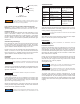
TROUBLESHOOTING
Problem
No or low
output
Unstable/low
output
Erratic
Operation
Works in
reverse
Output equals
supply
pressure
Look For
Zero Adjustment
Supply pressure too low
Electrical connection
Clogged orifice
Liquid/contamination in
air supply
Pressure goes down
when signal is increased
Improper pneumatic
connections
Solution
Reset zero
Increase supply pressure
(see specs)
Check connection/signal
Clean orifice
Clean air supply
Reverse input wires
Insure that supply is
connected to “IN” port
and output is connected
to “OUT” port
Apply the maximum input signal of the range being used (e.g. 20 mA).
Observe the output pressure. If necessary, adjust the span screw until
reaching maximum output pressure setting.
After setting the span it will be necessary to recheck the zero. Repeat
steps 1-4 until both end points are at required values.
MAINTENANCE
Instrument Air Filtration
Failures due to instrument supply air contamination are not covered by
warranty. Use of oil and/or water saturated instrument air can cause
erratic operation. Poor quality instrument air can result in unit failure. It
is recommended that a filter regulator (such as Dwyer Instruments, Inc.
Series AFR) be placed upstream of each unit where oil and/or water
laden instrument air is suspected.
If clean, dry air is not used the orifice can become blocked. To clean, first
turn off supply air, then remove the screw located on the side of the unit
above the “out” port. Unplug the orifice using a wire that has a smaller
diameter than 0.012˝ (0.30 mm). Replace
screw tightly into unit.
The Series 2700 Current to Pressure Transducers are not field
repairable and should be returned if repair is needed (field repair should
not be attempted and may void warranty). Be sure to include a brief
description of the problem plus any relevant application notes. Contact
customer service to receive a return goods authorization number before
shipping.
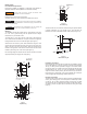
G
REEN LEAD (GROUND)
RED LEAD (+)
BLACK LEAD (–)
F
igure 4
1
/2˝ Conduit Connection
T
he I/P transducer enclosure contains aluminum and is
c
onsidered to constitute a potential risk of ignition by impact or
friction and must be taken into account during installation.
W
ARNING
Factory calibration is susceptible to shift due to handling during
transit. Dwyer Instruments, Inc. recommends that all units be
calibrated prior to use.
NOTICE
The unit must be calibrated in the plane it is mounted in.
NOTICE
If unable to achieve output during calibration process, turn zero
adjustment screw clockwise for up to 30 revolutions or until
output pressure rises.
NOTICE
Turn span screw clockwise to increase and counter-clockwise
to decrease.
NOTICE
U
nder normal circumstances, no maintenance should be
r
equired.
N
OTICE
If problems are not solved by troubleshooting procedures,
contact an applications engineer for further assistance.
NOTICE
These products are intended for use in industrial compressed-
air systems only. Do not use these products where pressures
and temperatures can exceed those listed under specifications.
WARNING