
User guide

INSTALLATION
Requirements
The Series 2900 transducer is suitable for installation in the following
locations: Intrinsically safe operation in hazardous locations outdoors
(NEMA 4X, CSA.ENC.4 & IP65) and Explosion-proof installation in
hazardous locations outdoors (NEMA 4X, CSA.ENC.4 & IP65).
Electrical Input: 4-20 mA DC current source. It is recommended that
shielded cable be used and that the shield be grounded to unit and earth
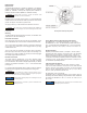
ground. See Figure 1 for location of ground screw.
Air Supply: Clean, dry, oil free instrument air filtered to 40 microns.
Mounting
The Series 2900 has been designed to mount inline, to a standard valve
yoke with the A-180 valve mounting kit.
Pneumatic Connections
Clean all pipe lines to remove dirt and scale prior to installation. Supply
air must be filtered to 40 microns and free of moisture and lubricants.
Two 1/4˝ NPT ports are provided for supply air connections. Either port
may be used. The unused port must be plugged with the pipe plug
included with the unit.
Two 1/4˝ NPT ports are provided for pneumatic output connections.
Either port may be used and one may be used for the mounting of an
output gage. If no gage is installed, the unused port must be plugged
with the pipe plug included with the unit.
Electrical Connections
The Series 2900 is supplied with a 1/2˝ NPT electrical conduit
connection. A two position terminal block that is wire ready is supplied
for 22-12 AWG wire. Wire should be stripped approximately 1/4˝ before
insertion. The terminals are labeled “+” and “–” on the terminal board
(see Figure 1).
It is recommended that shielded cable be used and that the shield be
grounded at the unit (ground screw provided) and to earth ground.
Factory Mutual Research (FM) Intrinsically Safe Ratings:
XP/I/1/BCD/T6 Ta = 70°C; DIP/II, III/1/EFG/T6 Ta = 70°C; IS/I, II,
III/1/CDEFG/T4 Ta = 70°C - 431-990-025 Entity; I/0/AEx ia IIB T4 Ta =
70°C - 431-990-025 Entity; NI/I/2/ABCD/T4 Ta = 70°C; Type 4X Entity
Parameters: Ui (Vmax) = 30 V, li (lmax) = 125 mA, Pi = 0.70 W, Ci = 0
mH
Equipment Ratings:
Explosion-proof for Class I Division 1, Groups B, C, and D. T6, Dust
Ignitionproof for Class I, Division 1, Groups E, F, and G, T6; Intrinsically
safe for Class I, II, and III, Division 1, Groups C, D, E, F, and G, T4
hazardous (classified) locations and intrinsically safe for Class I, Zone
0, Group IIB, T4 hazardous (classified) locations and suitable for Class
I, Groups A, B, C, D, T4, and Class II and III, Division 2, Groups F and
G, T6 hazardous (classified) locations.
CSA Intrinsically Safe Ratings:
Class I Division 1, Groups B, C, and D; Class I, Division 2, Groups
A, B, C and D; Class II, Division 1, Groups E, F, and G; Class II and III,
Division 2, Groups F and G. Rated 7 to 30 VDC, 4 to 20 mA; Enclosure
Type 4X; Type 4X; Temperature Code T6 (CL I Div 1). T4 (CL I, Div 2),
T6 (CL II, III, Div 2); Maximum Ambient 70°C.
Ex ia IIB (Class I, Zone 0, Group IIB)
Temperature Code T4; Maximum Ambient 70°C; Enclosure Type 4X;
Intrinsically Safe with the following entity Parameters when installed as
per drawing 531-990-0246 Ui = 30 V, li = 125 mA, Pi = 0.70 W, Ci = 0
µF, Li 0 mH.
Figure 1
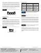
Zero Adjustment and Span Adjustment
A
ll wiring must be made to all local and national codes
a
ppropriate to the area of installation.
W
ARNING
Use caution not to scar threads of fitting during installation as
t
his can void integrity of the seal. Exhaust gas must be vented
t
o a safe area.
CAUTION
The I/P transducer enclosure contains aluminum and is
considered to constitute a potential risk of ignition by impact or
friction and must be taken into account during installation.
WARNING
Observe polarity. Reverse polarity will not damage the unit, but
unit will not operate.
NOTICE
Conduit should be connected to prevent condensation from
collecting in the unit.
CAUTION
Cable capacitance and inductance must be considered when
connecting to pressure transducer.
NOTICE