
User guide

1
. Control equipment connected to the Associated Apparatus
m
ust not use or generate more than 250 Vrms or VDC.
2
. The IS Barriers or Equipment (Associated Apparatus) must be Factory Mutual
Research Approved and the configuration of Associated Apparatus may be
installed within the Hazardous (Classified) location for which it is approved. The
Associated Apparatus and hazardous location loop apparatus manufacturer's
control drawings must be followed when installing this equipment. An AEx (ib)
A
ssociated Apparatus is suitable only for connection to Class I, Zone I,
H
azardous (Classified) Locations and is not suitable for Class I, Zone 0, or Class
I
, Division I Hazardous (Classified) Locations.
3. Installation should be in accordance with ANSI/ISA RP12.6 “Installation of
Intrinsically Safe Systems for Hazardous (Classified) Locations” and Article 500
of the National Electrical Code (ANSI/NFPA 70).
4. All units suitable for Type 4X installations.
5. The Intrinsic Safety Entity concept allows the interconnection of two FM
Approved intrinsically safe devices with entity parameters not specifically
examined in combination as a system when:
Ui or Vmax > Uo or Voc or Vt > 7.2 Volts
Ii or Imax > Io or Isc or It
Ca or Co > Ci + Ccable
La or Lo > Li + Lcable
Pi > Po
6. No revision to this drawing is permitted without prior Factory Mutual Research
Approval.
Hazardous Location Units:
FM & CSA
Explosion Proof:
Class I, Division 1, Groups B, C & D
Models 2913-E & 2916-E
Dust Ignition Proof:
Class II & III, Division 1, Groups E, F & G
Models 2913-E & 2916-E
ATEX (KEMA)
Explosion-proof/Intrinsically Safe Pending
EC Declaration of Conformity
RFI/EMI Effect: Less than .5% of span change in output pressure per En
61000-4-3:1998, Amendment 1, Performance Criterion A.
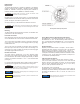
OPERATION
Calibration
All units are shipped from the factory calibrated, direct acting. If the user
requires a different mode of operation (i.e. reverse acting, split range) it
is necessary to reposition internal electrical dip switches located on the
circuit board (see Figure 1) as indicated in Figure 3.
Though the units are factory calibrated for direct acting operation, it is
suggested that the user check the calibration to ensure that settings and
operation match the application requirements.
Direct Acting Calibration
In direct acting operation the unit is calibrated so that minimum input
signal corresponds to minimum output pressure and increasing input
signal results in increasing output pressure.
Apply the minimum input signal of the range being used (e.g. 4 mA).
Observe the output pressure. If necessary, adjust the zero screw until
reaching minimum output pressure setting. Turn zero screw clockwise to
decrease and counter-clockwise to increase.
Apply the maximum input signal of the range being used (e.g. 20 mA).
Observe the output pressure. If necessary, adjust the span screw until
reaching maximum output pressure setting. After setting the span it will
be necessary to recheck the zero. Repeat steps until both end points are
at required values.
Reverse Acting Calibration
When calibrating to operate in the reverse acting mode the minimum
input signal produces the maximum output pressure and increasing the
input signal results in decreasing the output pressure. Setting the unit to
operate in the reverse acting mode is accomplished by positioning
internal electrical dip switches located on the circuit board (see Figure
1).
Entity Parameters:
Ui (Vmax) = 30 V
Ii (Imax) = 125 mA
Pi = 0.70 watts
Ci = 0 uF
Li = mH
Intrinsically Safe:
Class I, II & III, Division 1
Groups C, D, E, F & G
Models 2913-E & 2916-E
Suitable For:
Class I, II & III, Division 2,
Groups A, B, C, D, F & G
Models 2913-E & 2916-E
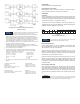
S
witch
ON
O
FF
1 2 3 4 5678910 11 12
Figure 3
D
irect Acting Switch Settings
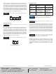
F
igure 2
F
actory Mutual and Canadian Standards Association I.S.
Installation Drawing
NOTICE
It is not necessary to remove the plastic cover of the unit for
calibration if the Direct Acting mode is desired.
NOTICE
Do not touch any components on circuit board except dip
switches. Do not reverse the input leads. Damage may occur.
Transducer fails in direct mode regardless of operating mode selected.
WARNING