
User guide

©Copyright 2013 Dwyer Instruments, Inc. Printed in U.S.A. 8/13 FR# R2-443363-00 Rev. 3
MAINTENANCE
Failures due to instrument supply air contamination are not covered by
warranty. Use of oil and/or water saturated instrument air can cause
erratic operation. Poor quality instrument air can result in unit failure. It
is recommended that a filter regulator (such as Dwyer Series AFR) be
placed upstream of each unit where oil and/or water laden instrument air
is suspected. If clean, dry air is not used the orifice can become blocked.
To clean, first turn off supply air, then remove the screw located on the
side of the unit above the “out” port. Unplug the orifice using a wire that
has a smaller diameter than 0.012˝ (0.30 mm). Replace screw tightly into
unit.
The Series 2900 Current to Pressure Transducers are not field
repairable and should be returned if repair is needed (field repair should
not be attempted and may void warranty). Be sure to include a brief
description of the problem plus any relevant application notes. Contact
customer service to receive a return goods authorization number before
shipping.
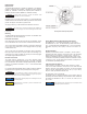
Access circuit board by first removing the die cast cover of the unit. Then
remove plastic cover by taking out two screws. Position the dip switches
as illustrated in Figure 4. Set the input signal to the minimum value being
used. Turn the zero screw to set the maximum output pressure. Turn
screw clockwise to decrease and counter-clockwise to increase. Set the
span by applying the maximum input signal. Turn the span screw to set
the minimum output pressure. Turn screw counter-clockwise to decrease
and clockwise to increase. It may be necessary to repeat steps until both
end points are at desired values. Replace both covers.
Split Range Calibration
When calibrated to operate in the split range mode a full input signal (i.e.
4-20 mA) will operate the unit at one half the normal output span (i.e. 3-
9 psig, 9-15 psig). Setting the unit to operate in the split range mode is
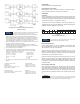
accomplished by positioning internal electrical dip switches. Access
circuit board by first removing the die cast cover of the unit. Then remove
plastic cover by taking out two screws. Position switches as illustrated in
Figure 5. Replace both covers. After replacing covers, refer to the
appropriate calibration procedure (Direct Acting or Reverse Acting) to get
to desired output range (i.e. 3-9 psig, 9-15 psig).
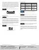
TROUBLESHOOTING
Problem
Sluggish
performance
Output won’t go
above 0
Output stays below
3 psi with increase
of input
Unit will not go full
scale with full-scale
input
Look For
Blocked orifice
No air input
Input leads reversed
Bad electrical connection
Circuit board failure
Insufficient supply pressure
Leak in connections
Circuit board failure
Solution
Clean external orifice
Check Instrument
air supply
Reverse input leads
Check input wiring
Factory Repair
Increase supply
pressure
Check connections
Factory Repair
Switch
ON
OFF
1 2
Figure 5
Split Range Switch Settings
F
igure 4
Reverse Acting Switch Settings
S
witch
O
N
O
FF
3 4 5 6 7 10
Switches not shown match Direct Acting Settings (see Figure
3).
N
OTICE
D
o not touch any components on circuit board except dip
s
witches.
W
ARNING
If problems are not solved by troubleshooting procedures,
contact an applications engineer for further assistance.
NOTICE
Under normal circumstances, no maintenance should be
required.
NOTICE
These products are intended for use in industrial compressed-
air systems only. Do not use these products where pressures
and temperatures can exceed those listed under specifications.
WARNING
Switches not shown match Direct Acting Settings (see Figure
3).
NOTICE
PROXIMITY CONTROLS
Phone: 219/879-8000 www.dwyer-inst.com
A DIVISION OF DWYER INSTRUMENTS, INC.
Fax: 219/872-9057 e-mail: info@dwyer-inst.com
P.O. BOX 373 • MICHIGAN CITY, INDIANA 46360, U.S.A.