
Manual

Photohelic
®
Differential Pressure Switch/Gage
Specifications — Installation and Operating Instructions
Bulletin E-70-A
DWYER INSTRUMENTS, INC.
Phone: 219/879-8000 www.dwyer-inst.com
P.O. BOX 373 • MICHIGAN CITY, INDIANA 46361, U.S.A. Fax: 219/872-9057 e-mail: info@dwyer-inst.com
O
.2O
.4O
.60
.80
1
.0
INCHES OF WATER
1/8 FEMALE NPT HIGH
PRESSURE CONNECTION
1/8 FEMALE NPT HIGH
PRESSURE CONNECTION
2-1/61
[52.39]
2
[50.80]
(4) 6-32 HOLES
EQUALLY SPACED ON A
5-1/8 [130.18] B.C.
1-1/4
[31.75]
Ø4-47/64
[120.25]
Ø5
[127.00]
Ø4 [101.60]
FACE
5-1/2 [139.70] O.D.
MOUNTING RING
5/8
[15.88]
1/8 FEMALE NPT LOW
PRESSURE CONNECTION
5/8 [15.88]
PANEL MAX
3/16
[4.76]
2-1/2
[63.50]
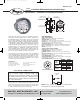
Using solid state technology, the Series 3000MRS Photohelic
®
switch/gage
combines the functions of a precise, highly repeat-
able differential pressure switch with a large easy-to-read analog
pressure gage employing the durable, time-proven Magnehelic
®
design. Switch setting is easy to adjust with large external knobs
on the gage face. Gage reading is unaffected by switch operation
— will indicate accurately even if power is interrupted. Solid state
design now results in greatly reduced size and weight. Units can
be flush mounted in 4
13
⁄16˝ (122 mm) hole or surface mounted with
hardware supplied. For applications requiring high cycle rates,
choose 3000MRS models with SPST (N.O.) solid state relays. All
models provide both low and high limit control and include 18-
inch (45 cm) cable assemblies for electrical connections.
Gage accuracy is ±2% of full scale and switch repeatability is
±1%. Switch deadband is one pointer width — less than 1% of full
scale. Compatible with air and other non-combustible, non-corro-
sive gases, they can be used in systems with pressures to 25 psig
(1.725 bar). Optional construction is available for use to either
35 psig (2.42 bar) or 80 psig (5.51 bar).
Accessories
Mounting ring, snap ring (4) 6-32 x 1
1
⁄4˝ RH machine screws
18˝ (45 cm) cable assembly (panel mounting)
(2)
3
⁄16˝ tubing to
1
⁄8˝ NPT adapters (3) 6-32 x
5
⁄16˝ RH machine screws
(2)
1
⁄8˝ NPT pipe plugs (surface mounting)
SPECIFICATIONS
GAGE SPECIFICATIONS
Service: Air and non-combustible, compatible gases.
Wetted Materials: Consult Factory.
Accuracy: ±2% of full scale (3000-0 ±3% of full scale).
Pressure Limit: -20˝ Hg. to 25 psig (-0.677 bar to 1.72 bar). MP option;
35 psig (2.41 bar), HP option; 80 psig (5.52 bar).
Temperature Limits: 20 to 120°F. (-6.67 to 48.9°C).
Process Connections: 1/8-27 female NPT (duplicated side and back).
Size: 4˝ (101.6 mm) dial face, 5˝ (127mm) O.D. x 3-1/8˝ (79.38 mm).
Weight: 1.8 Ib., (816 g).
SWITCH SPECIFICATIONS 3000MRS
Switch Type: Each setpoint has a solid state relay.
Switching Voltage: 20-280 VAC (47 - 63 Hz).
Switching Current: 1.0 amp (AC) max., 0.01 mA (AC) min, (2) SPST
N.O.
Electrical Connections: 18˝ (46 cm) cable assembly with 6 conductors,
Optional lengths to 100´ (30.5 m).
Power Requirements: 24 VDC, regulated ± 10%.
Mounting Orientation: Diaphragm in vertical position. Consult factory
for other position orientations.
Set Point Adjustment: Adjustable knobs on face.
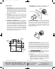
ELECTRICAL CONNECTIONS
CAUTION- Do not exceed specified electrical rat-
ings for supply voltage, switching voltage and
switching current. Permanent damage, not covered
by warranty, will result. This unit is designed to be
powered only by 24 VDC. Switched current must be
AC. See specifications.
Electrical connections are made by means of the cable assembly
supplied which has a multi-pin female plug installed on one end
which mates with the male connector on the rear of the gage. Wire
leads on the opposite end of the assembly are connected in
accordance with the drawing and chart to the right.
Note: An R/C snubber (P/N A-600) is recommended
for solenoid or contactor (inductive) loads.
A
B
C
D
E
F
DWYER
Series
3000 MRS
TO SET POINT
LEADS
(SEE NOTE)
LOAD
No Connection to H
LETTER
A
B
C
D
E
F
COLOR
Red
Black
Green
Blue
White
Orange
Power
Supply
Low
Set Point
High
Set Point
+
-
E-70-A:E-70-A 7/13/09 3:30 PM Page 1