
Manual

INSTALLATION
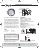
1. LOCATION: Select a location where the tempera-
ture of the unit will be between 20°F and 120°F. The
tubing feeding pressure to the instrument can be
run practically any length required but long lengths
will increase response time slightly. Avoid surfaces
with excessive vibration.
2. POSITION: All standard models are calibrated with
the diaphragm vertical and should be used in that
position for maximum accuracy. If your application
requires mounting in other than a vertical position,
be sure to specify this when ordering.
3. PRESSURE CONNECTIONS: For convenience,
two sets of 1/8˝ female NPT ports are available. Plug
the unused set with pipe plugs provided. Attach
tubing from positive pressure source to port marked
"HI" or from negative (Vacuum) source to port
marked "LOW". In either case, opposite port must
be vented to atmosphere. In dusty environments,
we recommend use of an A-331 Filter Vent Plug to
keep interior of instrument clean. For differential
pressures the higher source is connected to the "HI"
port and lower to the "LOW" port.
4. MOUNTING: The Photohelic
®
Switch/Gage may
be either panel mounted or surface mounted.
A. PANEL MOUNTING: Cut a 4-3/4˝ or 120mm dia.
hole in panel and insert the complete unit from the
front. Slip on the mounting ring and install the split
snap ring in the groove on the bezel. Seat the mount-
ing ring against the snap ring and thread the four
screws through the tapped holes. Tighten screws
against rear of panel.
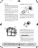
B. SURFACE MOUNTING: Drill (3) 3/16˝ dia. holes for
mounting screws and (1) 7/8˝ dia. hole for wire assem-
bly as shown in hole location drawing. Insert screws
from rear of panel and thread into tapped holes on
back of Photohelic
®
Switch/Gage case. If rear pressure
connections are to be used, make 1/2˝ dia. holes locat-
ed as shown in hole location drawing in left column.
Once Photohelic
®
Switch/Gage unit is securely mount-
ed, plug wire assembly into 7 pin connector on rear of
unit, being careful to match pin locations.
5. ZEROING: Once the Photohelic
®
Switch/Gage is
mounted in its final position, check to be sure point-
er aligns with zero on scale, when no pressure is
applied and both low and high pressure ports are
vented to atmosphere. To adjust, turn small slotted
screw at center-bottom of gage face.
©Copyright 2009 Dwyer Instruments, Inc. Printed in U.S.A. 7/09 FR# 13-440658-00 Rev. 3
Ø4-3/4 [120.65] HOLE
SNAP RING
GROOVE
PNEUMATIC
PRESSURE TAPS
Ø7/8 [22.23]
HOLE IN PANEL
FOR WIRE
CONNECTION
1-1/8
[28.58]
11/16
[17.46]
1-1/8
[28.58]
Ø1/2 [12.70]
HOLE FOR
HIGH PRESSURE
CONNECTION
1-3/4
[44.45]
1/2
[12.70]
Ø1/2 [12.70] HOLE FOR
LOW PRESSURE CONNECTION
(3) Ø3/16 [4.77]
HOLES EQUALLY
SPACED ON
A 4-1/8 [104.78] B.C.
DWYER INSTRUMENTS, INC.
Phone: 219/879-8000 www.dwyer-inst.com
P.O. BOX 373 • MICHIGAN CITY, INDIANA 46361, U.S.A. Fax: 219/872-9057 e-mail: info@dwyer-inst.com
E-70-A:E-70-A 7/13/09 3:30 PM Page 2