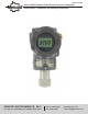
Bulletin P-3200 Series 3200 Explosion-Proof Smart Pressure Transmitter Specifications - Installation and Operating Instructions DWYER INSTRUMENTS, INC. P.O. BOX 373 • MICHIGAN CITY, INDIANA 46360, U.S.A. Phone: 219/879-8000 Fax: 219/872-9057 www.dwyer-inst.com e-mail: info@dwyermail.
Table of Contents Chapter 5. On-line Operation 5.1 Overview 5.2 Safety Messages 5.3 Configuration Data Review 5.4 Check Output 5.5 Basic Setup 5.6 Detail Setup 5.7 Information Variables Setup 5.8 Diagnostics and Services 5.9 Calibration Chapter 1. Introduction 1.1 Using This Manual 1.2 Overview of Transmitter 1.3 Software Compatibility 1.4 Transmitter Components Chapter 2. Handling Cautions 2.1 Unpacking Transmitters and Specifications Check 2.2 Models and Specifications Check 2.3 Storage 2.
1.2 Overview of Transmitter The Mercoid® Smart Pressure Transmitter is a microprocessor based pressure transmitter with a capacitance sensor optimized for draft measurement. The Model 3200 has a true draft analog range from 0 to 20 mA. This transmitter is explosion-proof, high precision accuracy, reliability and has digital communication for remote communication system. The Model 3200 is enabled with HART® communication with Host, HHT (HART® Communicator) or PC Configurator.
Chapter 2 Handling Cautions This chapter consists of cautions for transmitter handling, storage, installation, insulation and explosion structure, etc.
2.5 Calibration on Spot after Installation 1. Sensor Zero Trim should be done after transmitter is installed, because the zero point is not configured for mounting status. 2. When calibrating the Sensor Zero Trim apply a pressure of zero in advance, Sensor Zero Trim the sensor when the pressure is sufficiently stabilized (after approximately 10 seconds). 3. Sensor Zero Trimming can also be done with the Zero/Span button or a HHT (HART® Communicator), PC or PDA configurator. 4.
2. Operating Temperature : -20°C ≤ Tamb ≤ +60°C 3. T6 for process ≤ 85°C; 4. T5 for process ≤ 100°C; 5. T4 for process ≤ 130°C; 2.9 Insulation Resistance Test and Dielectric Strength Test Since the transmitter has undergone insulation resistance and dielectric strength tests at the factory, normally these tests are not required. However, if required, observe the following precautions in the test procedures. NOTICE Electrical Data 1. Supply Voltage : 42 Vdc Max 2. Output Signal : 4 to 20 mA + HART 1.
3.2 Safety Message Procedures and instructions in this chapter may require special precautions to ensure the safety of the personnel performing the operations. Potential safety issues are indicated by a warning symbol (▲). Refer to the following safety messages before performing an operation preceded by this symbol. 3.3 Warning WARNING Explosion can result in death or serious injury: • Do not remove the transmitter covers in explosion environments when the circuit is powered.
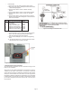
• 3.7 Configuration of Zero and Span Procedures The ZERO and SPAN buttons are under the transmitter’s nameplate. The ZERO, SPAN, ZERO TRIM, ZERO ADJ, Units, Range, Dampening, LCD and decimal set functions are configurable using the ZERO / SPAN buttons. • Zero/Span Configuration Process Remove both name plate screws on the upper part of transmitter. Remove top name plate to access the Zero and Span Buttons. (following Figure 3-4) Press the button for 3 seconds to execute each function.
• 5. Exercises for each function • ZERO TRIM 1. Access the menu by pressing the Zero+Span buttons. 2. Move to the sub directory using the Span button until the 1 TRIM message appears on the display. 3. Change the Zero Trim Function by using the Span button until the 11 Z-TRIM message appears on the display. • ZERO ADJUSTMENT : Change the PV value to 14 1. Exit the menu by pressing the Zero+Span button. 2. Moving thru the sub directory using the Span button until 1 TRIM message appears. 3.
• Decimal Place 1. Access the menu by pressing the Zero+Span buttons. 2. Move to the next menu by pressing the Zero button until the 1 TRIM message appears 3. Press the Span button until the 2 SETUP message appears. 4. Press the Span button until the 3 LCD message appears. 5. Press the Span button until the 31 DEC-PL message appears. 6. Press the Span button until the Decimal Place message appears, the decimal place will appear on the second line of the LCD as follows.
Chapter 4 Installation 4.1 Overview The information in Chapter 4 explains installation. Start Do you want 4.2 Safety Message Procedures and instructions in this chapter may require special safety measures to ensure the safety of the personnel performing the operation. Potential installation safety issues are indicated by a warning symbol (▲). Refer to the following safety messages before installing the 3200 pressure transmitter. Yes Basic Setup a) Unit Setup b) Range Setup 4.
4.7 Wiring 4.7.1 Wiring Caution 1. Install the signal cables away from potential sources of electrical noise such as transformers, electrical motors, etc. 2. Before wiring, remove electrical conduit cap. 3. All screwed connections on the housing must be sealed with waterproof sealant. We recommend use of silicone based sealants to minimize post- hardening. 4. Avoid running DC signal and AC power cables in the same ducts/cable conduits to avoid signal noise issues. 5.
B.Wiring Installation General-use (Figure 4-4a) 1. Use metallic conduit or waterproof cable glands for wiring. a. Apply non-hardening sealant to the terminal box and the threads on the flexible metal conduit for waterproofing. 4.7.5 Grounding a. Grounding should satisfy KS requirements (grounding resistance should be 10 ohm or less). Grounding is required for explosion-proof applications and the ground resistance must be below 10 ohms. b.
4.8 Mechanical Considerations Figure 4-6 is a dimensional drawing for the 3200. Figure 4-7 shows how the A-630 angle bracket is mounted to a pipe. 112 mm 86 mm 73 mm 4.9 Environmental Considerations 4.9.1 Ambient Temperature The transmitter ambient temperature range is 4 to 180°F (-20 to 60°C). If the ambient temperature is going to exceed the temperature range, precautions must be taken to keep the temperature within the temperature limits. 39 mm 4.9.
5.5 Basic Setup The correlation variable must be configured before operating the transmitter. 5.8 Configuration of Breakdown Diagnostic Function 5.8.1 Loop Test The Loop Test verifies the output of the transmitter, the integrity of the loop, and the operation of any recorders or similar devices installed in the loop. The following procedures are required for a loop test. 5.5.1 Select Sensor Range The pressure range must be selected when ordering the pressure transmitter. 5.5.
Chapter 6 Maintenance 6.1 Overview This chapter describes diagnostic and maintenance. 6.2 Safety Message When the transmitter is in operation, operators should follow all safety messages. Potential safety issues are indicated by a warning symbol (▲). Refer to the following safety messages before performing any operation proceeded by a (▲) symbol. 6.2.
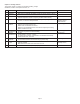
6.3 Hardware Diagnostics If there is a failure dispite a diagnostic message on the HHT, Table 6.1 can help troubleshoot the problem. Symptom Transmitter does not Communicate with HART® Communicator High Output Erratic Output Low Output or No Output Corrective Action • Check for a 250-550 ohms resistance between the power supply and HHT. • Check for adequate voltage to the transmitter (the transmitter requires 11.9 ~ 45 Vdc). • Check for intermittent shorts, open circuits, and multiple grounds.
6.4 Hardware Maintenance The Mercoid® 3200 Smart Transmitter has no moving parts and requires little maintenance. If a transmitter fails, it must be retuned to Dwyer Instruments, Inc. for inspection, repair, or replacement. 6.4.1 Test Terminals The test terminals are marked TEST on the terminal block. The test and negative terminals are connected to the power terminals; so long as the voltage across the receptacles are below the diode threshold voltage, no current will pass through the diode.
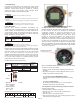
6.4.2.2 Fail Mode Jumper Switch and EEPROM-Write Fail-mode jumper switch and EEPROM-Write is located behind the front cover.
©Copyright 2014 Dwyer Instruments, Inc. DWYER INSTRUMENTS, INC. P.O. BOX 373 • MICHIGAN CITY, INDIANA 46360, U.S.A. Printed in U.S.A. 5/14 Phone: 219/879-8000 Fax: 219/872-9057 FR# R6-443809-00 Rev. 4 www.dwyer-inst.com e-mail: info@dwyermail.