
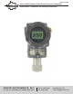
Manual

Page 3
Chapter 2 Handling Cautions
This chapter consists of cautions for transmitter handling, storage,
installation, insulation and explosion structure, etc.
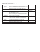
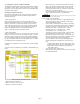
Step
1
2
3
4
5
6
7
8
9
11
Job
Unpacking
Model and
S
pecifications
Storage
Calibration
Installation
Locations
Mechanical
Considerations
Electrical
Considerations
Mounting and
Installation
Calibration
on Spot
Operation
Job Details
- Unpack transmitter packing
- Make sure the transmitter nameplate matches the model number on the PO
- In a dry, non-vibration and non-impact area
- Ambient temperature around 77°F (25°C) and 65% relative humidity
- Configuration of the Range, Zero/Span, Unit, Tag, Dampening Time, Transfer
Function, DA Trim and other parameters
- Where ambient temperature are consistant
- Exposure to chemical corrosion, etc.
- Where shock and vibration are minimal
- Where the area classification does not exceed the exposion-proof rating
- Where maintenance is easy
-
Where transmitter can be handled easily
- Be cautious of process connections leaking
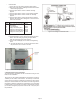
- 24 VDC
(Power Supply is 11.9 Vdc – 45 Vdc)
- For HART
®
communication, total resistance on transmitter terminal loop
should between 250 – 550 Ohm
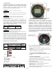
- When mounting the transmitter, an appropriate bracket should be used
- The transmitter should be mounted securely to prevent swing
- Sensor Zero Trim should be done after ten seconds after the differential
pressure stabilizes
- Make sure that PV value is zero and current is 4 mA
- Make sure the transmitter operates properly
Instrument
- HHT
-Pressure Source
- Galvanometer
(Engineering)
(Engineering)
(Engineering)
(Mounting and Installation)
HHT or
Zero/Span button
Eye or HHT