
Manual

Page 5
2.9 Insulation Resistance Test and Dielectric Strength Test
Since the transmitter has undergone insulation resistance and
dielectric strength tests at the factory, normally these tests are not
required. However, if required, observe the following precautions in
the test procedures.
1. Do not perform such tests more frequently than necessary. Even
test voltages, that do not cause visible damage to the insulation,
may degrade the insulation and reduce safety margins.
2. Never apply a voltage exceeding 500VDC for the insulation
resistance test, or a voltage exceeding 500VAC for the dielectric
s
trength test.
3. Before conducting these tests, disconnect all signal lines from the
transmitter terminals. Perform the tests using the following
procedure.
Insulation Resistance test
1. Short-circuit the + and - SUPPLY terminals in the terminal
box.
2. Turn OFF the insulation tester. Then connect the insulation
tester plus (+) lead wire to the shorted SUPPLY terminals and
the minus (-) lead wire to the grounding terminal.
3. Turn ON the insulation tester power and measure the insulation
resistance. The voltage should be applied briefly to verify that
insulation resistance is at least 20MΩ.
4. After completing the test and being very careful not to touch
exposed conductors. Disconnect the insulation tester and
connect a 100kW resistor between the grounding terminal and
the short-circuiting SUPPLY terminals. Leave this resistor
connected at least three seconds to discharge any static
potential. Do not touch the terminal while it is discharging.
Dielectric Strength Test
1. Short-circuit the + and - SUPPLY terminals in the terminal
box.
2. Turn off the dielectric strength tester. Then connect the tester
between the shorted SUPPLY terminal and the grounding
terminal. Be sure to connect the grounding lead of the dielectric
strength tester to the ground terminal.
3. Set the current limit on the dielectric strength tester to 10mA,
then turn on the power and gradually increase the tester
voltage from '0' to the specified voltage.
4. When the specified voltage is reached, hold it for one minute.
5. After completing this test, slowly decrease the voltage to avoid
any voltage surges.
2.10 Explosion-Proof Rating
2-10-1. FM Certification
HAZARDOUS LOCATION ELECTRICAL EQUIPMENT
Equipment Rating : Explosion-Proof for use in Class I, Division 1,
Groups A, B, C and D;
Dust-Ignition-Proof for Class II/III, Division 1, Groups E, F and G;
Nonincensive for use in Class I, Division 2, Groups A, B, C and D;
Suitable for use in Class II, Division 2, Groups E, F and G; and
Suitable for Class III, Division 1;
Hazardous(classified) location, indoor and outdoor (NEMA Type
4X/IP67).
2.10.2 DEKRA/ATEX Certification
ATEX Certification number : DEKRA 11ATEX0192X
CE 0344 II 2 G
Model 3200 for potentially explosive
atmosphere
1. Ex d IIC T6...T4
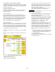
2. Operating Temperature : -20°C ≤ T
amb
≤ +60°C
3. T6 for process ≤ 85°C;
4. T5 for process ≤ 100°C;
5. T4 for process ≤ 130°C;
Electrical Data
1. Supply Voltage : 42 Vdc Max
2. Output Signal : 4 to 20 mA + HART
Electrical Connection : 1/2˝-14 NPT Female
3
200 ATEX Certification is according to the
below standards
EN 60079-0 : 2006
EN 60079-1 : 2007
Installation
1. All wiring shall comply with local installation requirement.
2. The cable glands and blanking elements shall be of a certified
flameproof type, suitable for the condition of use and correctly
installed. Also those devices should be endured at the 130°C.
3. Housing Ground must be followed to “local electrical codes”. The
most efficient ground procedure is to connect directly to the earth
as least impedance.
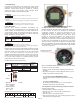
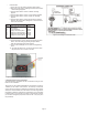
1. How to Housing Ground:
A. Internal Ground Connection:
Internal ground connection screw is located in terminal in
housing; the screw can be identified as ground sign.
B. External Ground Assembly:
This is located in the right side of housing and identified as
ground sign. (Grounding with a cable lug)
2. When use tubing, stopping boxes must be connected with the wall
of housing directly.
3. Tubing is installed a minimum of 5 threads.
4. Sensor is to be threaded a minimum of 7 threads and prevented
from turing by tightening the housing rotation set screw.
5. Do not disassemble flameproof Joints but in an unavoidable case
to disassemble it or need the specification of flameproof Joints,
contact the manufacturer before doing.
Operation
1. Take care not to generate mechanical spark when access to the
instrument and peripheral devices in hazardous location.
2.11 EMC Conformity Standards
EMI (Emission): EN55011
EMS (Immunity): EN50082-2
Dwyer Instruments, Inc. recommends customer use metal conduit
wiring or twisted pair shield cable for signal wiring to conform with
EMC regulation, when installing the Mercoid
®
3200 transmitters.
Chapter 3 Transmitter Functions
3.1 Overview
This chapter contains information on operating the Model 3200.
Tasks that should be performed on the bench prior to installation are
explained in this chapter.
NOTICE
NOTICE
NOTICE
NOTICE
NOTICE
NOTICE
DO NOT OPEN WHEN AN EXPLOSIVE
ATMOSPHERE MAY BE PRESENT.
WARNING
Maintenance and Repair
The instrument modification or parts replacement by other than
authorized representative of Dwyer/Mercoid is prohobited and will void KEMA/ATEX
explosion-proof/flame-proof.
NOTICE