
Manual

Page 6
3.2 Safety Message
Procedures and instructions in this chapter may require special
precautions to ensure the safety of the personnel performing the
operations. Potential safety issues are indicated by a warning
symbol (▲). Refer to the following safety messages before
performing an operation preceded by this symbol.
3.3 Warning
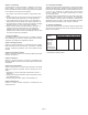
3.4 Fail Mode Alarm
Mercoid
®
Smart Pressure Transmitter automatically and
continuously performs self-diagnostic test. If the self-diagnostic test
detects a failure, the transmitter drives the output outside of the
normal operation values. The transmitter will drive its output low
(down) or high (up) based on the position of the failure mode alarm
jumper. See Table 3.1 for output values.
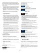
[Table 3.1 Standard Alarm and Saturation Values]
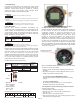
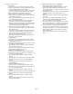
Fail Safe mode can be set via Jumper switches provided on the LCD
module or the main CPU module. The jumper switch for an indicating
transmitter, located on the LCD module, can be set to the right (fail
down i.e. ≤ 3.75 mA) or left (fail up i.e. ≥ 21.75 mA). For non-
indicating transmitters the jumper switch is located on the main CPU
module, it can be set up (fail up to ≥ 21.75 mA) or down (fail down
to ≤ 3.75 mA). Refer to Figure 3-1 for detailed summary of jumper
settings for both CPU and LCD modules.
Fail Mode Selection (LCD & CPU Module)
1. WR_EN (EEPROM Write Enable)
DOWN : ENABLE
UP : DISABLE
2. Fial Mode (Alarm)
DOWN : LOW
UP : HIGH
3-5 EEProm-Write Enable / Disable Mode Switch
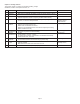
EEPROM (Electrically Erasable Programmable ROM), included on
the CPU module, is used by the transmitter to save/restore
configuration variables. To protect the transmitter from any
unauthorized changes, a hardware lockout feature can be
implemented by using the Write-Protect mode jumper switch
provided on the main CPU Module. This Jumper switch is
designated as “EEP-Write DIS/EN” on the CPU Module. If the
jumper switch is connected to DIS, this disables writing/changing of
any data saved in the EEPROM. On the other hand, if the jumper
switch is set to “EN”, changes can be made to the configuration data
stored in the EEPROM. The factory default setting is “EN” (Enable)
for all transmitters. The location of the Wire Protect Jumper Switch
can be seen in Figure 3-3.
The 3200 has two security settings.
1. Security Jumper: the transmitter configuration parameters are
protected.
2. Physically removing Zero and Span Magnetic Buttons: you are
unable to regulate zero and span locally.
3.5.1 Security Jumper (EEPROM Write Protect)
Prevents the transmitter’s configured parameters from being
changed.
3.5.2 Zero and Span Buttons
By removing the Magnetic Buttons, you can't configure the
transmitter using the Zero and Span locally.
3.6 Configuration of Alarm and Security Jumper Procedures
Changing jumper position.
1. If the transmitter is installed, cutoff power.
2. Open the front cover. If the transmitter is powered, don't
open the cover.
3. Move the jumper to the preferred position.
4. Close the front housing cover. You must fully engage the cover to
meet explosion-proof requirements.
Level
Low/Down
High/Up
4~20mA Saturation
3.9 mA
20.8 mA
4~20mA Alarm
≤ 3.75 mA
≥ 21.75 mA
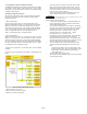
Select Fail
Mode
Fail Down
Fail Up
CPU Module
Down
Down
Up
Both LCD Module and CPU Module
LCD Module
D
U
U or D
Only CPU
Module
CPU Module
D
U
UP
DOWN
U O O O O O O D O O O D
Fail Mode for LCD Module Selection Jumper Switch
Figure 3-1. Fail Mode and EEPROM-Write Selection Jumper Switch
(If Down)
FAIL MODE
(If Up)
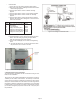
Figure 3-2 Fail Mode Selection Jumper Switch for LCD Module
Figure 3-3. CPU Module Fail Mode, EEPROM-Write Selection Jumper Switch
Electrical shock can result in serious injury:
• Avoid contact with the leads and terminals. High voltage, that
may be present, on leads can cause electrical shock.
WARNING
Explosion can result in death or serious injury:
•
Do not remove the transmitter covers in explosion environments when the circuit
i
s powered.
•
Transmitter covers must be fully engaged to meet explosion-proof requirements.
W
ARNING
Electrical shock can result in death or serious injury:
• Only qualified personnel can install the transmitter.
W
ARNING