
Instruction Manual

Parts list. Contact factory for ordering information.
1. Mount Gage securely on a vertical surface, avoiding excessive heat.
(Temperatures over 150ºF (66ºC), will damage gage). Level gage
approximately by swinging gage about top center mounting screw
and locate bottom bracket screws in center of slot.
2. Turn connectors counter clockwise 1/2 to 3/4 turns, thus venting gage
to atmosphere.
3. Center bubble between guide lines on spirit level by swinging about
top center mounting screw and tighten bottom bracket screws.
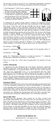
4. Turn fluid level adjustment knob to set the meniscus of the fluid
column at zero, as shown below.
Align fluid meniscus and the reflected image to eliminate parallax error.
5. Add or remove fluid as necessary.
6. Use left hand gage connection for plus (above atmospheric)
pressures. Connect to right side for minus (below atmospheric)
pressures. Connect to both sides for differential pressures, as with a
Pitot tube.
CAUTION:
Use only Dwyer gage fluid. See gage scale plate for proper specific
gravity. Clean only with mild soap and water. Strong liquid soaps and other
fluids or cleaning agents may damage the gage. Maximum pressure 100
psi.
AIR VELOCITY
The total pressure of an air stream flowing in a duct is the sum of the static
or bursting pressure exerted upon the sidewalls of the duct and the impact
or velocity pressure of the moving air. Through the use of a Pitot tube
connected differentially to a manometer, the velocity pressure alone is
indicated and the corresponding air velocity determined.
2
4
3
2
1
6
5
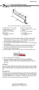
Series 424 Stationary Gage
O
perating Instructions and Parts List
B
ulletin D-4
DWYER INSTRUMENTS INC.
MICHIGAN CITY, IN 46360 U.S.A.
1) Gage body, 5˝ or 10˝ range
2) Molded Nylon Connector –
Rapid shut off type
3) Scale, 5˝ or 10˝ range
4) Mounting
5) Fluid level adjustment
assembly
6) Gage leveling bracket
7) Vinyl tubing 3/16˝ I.D. 3 ft. (not
shown)
8) 1/8˝ NPT Tube Adapter
(not shown)
9) 1 oz. bottle gage fluid
(not shown)