
Install Instructions
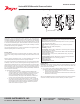

Series ADPS Differential Pressure Switch
Specications - Installation and Operating Instructions
Bulletin E-80-ADPS
The Series ADPS Adjustable Differential Pressure Switch is designed for
overpressure, vacuum, and differential pressure applications. The scaled adjustment
knob allows changes to the switching pressure to be made without a pressure gage.
The ADPS is available with settings from 0.08 in w.c. (20 Pa) to 20 in w.c. (5000 Pa).
The silicone diaphragm and PA 6.6 body make the Series ADPS perfect for use with
air and other noncombustible gases. The Series ADPS can be used in monitoring air
lters, ventilators, and industrial cooling-air circuits along with controlling air and re-
protection aps and many other applications.
Use only with mediums such as air, or other noncombustible or non-aggressive gases.
Otherwise operating faults or accidents may occur.
Mounting Switch
First check the pressure switch to ascertain whether any damage is visible on the
housing. If the housing is leaky because of damage, the pressure switch must not be
used.
Switching pressure specications apply to vertical installation which is also the
recommended position with pressure connections pointing downwards.
Only if there is no potential for condensate forming can you mount the pressure switch
horizontally. In this case, however, the switching values are approximately 0.08 in w.c.
(20 Pa) higher as indicated on the scale. In the horizontal position, the pressure switch
should be mounted ‘lying down’ only (that is to say with the electrical connections
pointing upwards). Do not mount the pressure switch in a hanging position (that is to
say, not ‘overhead’ with the electrical connections pointing downwards). Otherwise the
device will function inaccurately.
a) Mounting with screws or brackets
1. To mount the pressure switch, L-shaped A-288 and S-shaped A-289
mounting brackets can be ordered separately. To secure the device on the
rear side of the housing, only use the sheet metal screws (3.5 x 8 mm)
which are supplied together with the mounting brackets. Under no
circumstances must you use longer screws. Otherwise, the base of the
housing could be punctured resulting in the pressure switch leaking.
2. You can also mount the pressure switch directly on a wall. To do this use
screws with a maximum diameter of 0.315˝ (8.0 mm), if you use the outer
mounting lugs to screw the device in place. Do not tighten the screws so
much that the base of the device is deformed. Otherwise, the pressure
switch can be shifted out of position, or leak.
Installing Hoses
Important: Pressure tubing cannot be kinked. Pay particular attention to this point if
you run hoses over an edge. It is better to form a loop. If the hoses are kinked, the
device cannot function accurately.
a) For connection to the pressure switch two ttings inherent in the housing are
provided for hoses with an internal diameter of 1/4˝ (6.0 mm).
1. Connect a hose with the higher pressure to socket P1 which is located on
the lower section of the housing.
2. Connect a hose with the lower pressure to socket P2 which is located on the
middle section of the housing.
After you have installed the hoses, it is absolutely essential to check them for tightness
of t at the connection points and to make sure that they run without any kinks.
SPECIFICATIONS
Service: Air and noncombustible, compatible gases.
Wetted Materials: Diaphragm material: Silicone; Housing material and switch body:
POM and PA 6.6; Cover: Polystyrene.
Temperature Limits: Process and ambient temperature: -4 to 185°F (-20 to 85°C);
Storage: -40 to 185°F (-40 to 85°C).
Pressure Limits: Max operating pressure: 40 in w.c. (10 kPa) for all pressure
ranges.
Switch Type: Single-pole double-throw (SPDT).
Repeatability: ±15% FS.
Electrical Rating: Standard: Max, 1.5A/250 VAC, max switching rate: 6 cycles/min;
Gold contact option: 0.1 A/ 24 VDC.
Electrical Connections: Push-on screw terminals. M20x1.5 with cable strain relief
or optional 1/2˝ NPT connection.
Process Connections: 5/16˝ (7.94 mm) outside diameter tubing, 1/4˝ (6.0 mm)
inside diameter tubing.
Mounting Orientation: Vertically, with pressure connections pointing downwards.
Mechanical Working Life: Over 10
6
switching operations.
Weight: 4.4 oz (125 g).
Enclosure Rating: IP54.
Agency Approvals: CE, RoHS.
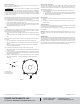
CABLE GLAND INSERT
+
[P1]
-
[P2]
1-31/32 [50]
2-9/16 [65]
2-1/4 [57]
45/64
[18]
Ø11/64
[Ø4.5]
21/64
[8.5]
51/64 [18]
9/32 [7]
2-21/64
[59]
Ø15/64
[Ø6]
DWYER INSTRUMENTS, INC.
P.O. BOX 373 • MICHIGAN CITY, INDIANA 46360, U.S.A.
Phone: 219-879-8000
Fax: 219-872-9057
www.dwyer-inst.com
e-mail: info@dwyermail.com