
Install Instructions

Printed in U.S.A. 4/20 FR# 443602-00 Rev. 3©Copyright 2020 Dwyer Instruments, Inc.
DWYER INSTRUMENTS, INC.
P.O. BOX 373 • MICHIGAN CITY, INDIANA 46360, U.S.A.
Phone: 219-879-8000
Fax: 219-872-9057
www.dwyer-inst.com
e-mail: info@dwyermail.com
Electrical Connection
Work on electrical installations must only be carried out by electricians who are
specically trained for this purpose.
For cable gland models, the seal in the screw cable connection is designed for cables
with alternative sheath diameters of 0.275˝ (7 mm) or 0.393˝ (10 mm). Only use these
sizes – otherwise the screw cable connection cannot seal adequately.
1. If using a 0.275˝ (7 mm) connecting cable, you can line up the press nut, the plain
washer and the sealing ring directly on the cable.
2. If using a 0.393˝ (10 mm) connecting cable, you must rst break the inner rubber
ring out of the sealing ring directly on the cable. Then line up the press nut, the
plain washer and the sealing ring on the cable.
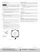
Wiring
The switching device in this pressure switch is designed as a change-over contact as
can be seen from the wiring diagram (Figure 1). The rest position is shown in Figure 1
(pressure below the activation switch point on dial).
1. In the instance where pole 3 (COM) closes to Pole 2, the pressure is increasing
(NO).
2. In the instance where pole 3 (COM) closes to Pole 1, the pressure is decreasing
(NC).
Protect the feed line (to pole 3) by fuse, either in control system or along the line, and
do so with:
1. Max 1.5 A / 250 VAC, if you are loading the contact with an resistive load.
2. Max 0.4 A / 250 VAC, if you are loading the contact with an inductive load (such
as relay).
3. Max 0.1 A / 24 VDC, if you are using the pressure switch in the weak current
version with gold-plated contacts.
The connections are intended for crimp-type sockets, 0.25 in (6.3 mm).
1. Make sure the crimp connection is perfect, and that the cable lugs t properly on
to the connections.
2. If you do not have any crimp-type sockets available, you can also use the cable
lugs which are supplied with mounted screw terminals. However, these are only
intended for rigid copper wire.
3. On ex, it is either necessary to crimp on strand end sleeves – and then you can
also screw the strands on – or to crimp cable lugs on directly as previously
described.
Setting the Pressure Range
Make absolutely certain that there is no voltage on the electrical connections before
you carry out any setting on the pressure switch. Otherwise, it could be fatal if you
accidentally touch the electrical connections or the metal adjusting screw while you
are performing the settings.
a) Use the adjustment dial to set the pressure which should trip the switch on an
increase of pressure.
1. The indications on the dial are only correct for the vertical mounting position.
2. When the pressure falls, the switch returns to its resting position as soon as
the pressure falls below the dead band.
Attaching Cover
a) Insert the screw cable connection into the recess provided for this purpose on the
housing.
b) Then place the housing cover in position and screw it down evenly on to the
pressure switch.
Testing the Setting
Do not operate the system until the housing is closed. Otherwise there is the possibility
of an electric shock if you accidentally touch live parts.
Check the trip and reset pressures by slowly increasing the pressure and then allowing
it to fall again.
Important: Observe the maximum permissible operating pressure of 40 in w.c. (10
kPa) which is indicated in the data sheet. Otherwise the pressure switch may be
damaged.
MAINTENANCE
Upon nal installation of the Series ADPS Adjustable Differential Pressure Switch, no
routine maintenance is required. A periodic check of system operation is recommended.
The Series ADPS is not eld serviceable and should be returned if repair is needed
(eld repair should not be attempted and may void warranty). Be sure to include a
brief description of the problem plus any relevant application notes. Contact customer
service to receive a return goods authorization number before shipping.
Figure 1
1. Break contact
2. Operating contact
3. Power supply line
First make sure that there is no voltage on the connecting cable
while you are working on the electrical connections. Otherwise, a
possible electric shock may result and the connected equipment may be damaged.
The connecting cable can be run to the pressure switch from three sides, according
to choice. The screw cable connection has a plug-in design for this purpose. Rotate
protective cover accordingly.
CAUTION
1
2
3
2 NO
1 NC
3 COM
P