
User Manual
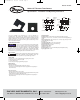

OUTPUT WIRING
• Connect control or monitoring wires to the sensor.
• Use 14 to 22 AWG copper wire.
• Tighten terminals securely.
• Be sure the output load or loop requirements are met.
RANGE SELECTION
For models that feature field selectable ranges:
• Determine the normal operating amperage of the monitored circuit.
• Select the range that is equal to or slightly higher than the normal operating
amperage.
• Place the range jumper in the appropriate position according to selection.
TROUBLESHOOTING
MAINTENANCE
Upon final installation of the Series CCT Current Transformers, no routine
maintenance is required. A periodic check of system calibration is recommended. The
Series CCT is not field serviceable and should be returned if repair is needed (field
repair should not be attempted and may void warranty). Be sure to include a brief
description of the problem plus any relevant application notes. Contact customer
service to receive a return of goods authorization number before shipping.
DWYER INSTRUMENTS, INC.
Phone: 219/879-8000 www.dwyer-inst.com
P.O. BOX 373 • MICHIGAN CITY, INDIANA 46361, U.S.A. Fax: 219/872-9057 e-mail: info@dwyer-inst.com
©Copyright 2010 Dwyer Instruments, Inc. Printed in U.S.A. 11/10 FR# R6-443843-00 Rev.1
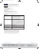
Symptom
Sensor has no output.
Output signal is too low.
Output signal is always at maximum.
Sensor is always at 4 mA.
Output signal is always at 20 mA.
Solution
• Polarity is not properly matched. Check and correct wiring polarity.
• For Model CCT40/50-102/202/203: Monitored load is not AC or is
not on. Check that the monitored AC load is on.
• For Model CTXX-100/200: Power supply is not properly sized.
Check power supply current and voltage rating.
• For Model CCTXX-100/102: The core contact area may be dirty.
Open the sensor and clean the contact area.
• The jumper may be set in a range that is too high for current being
monitored. Move the jumper to the correct range.
• Monitored current is below minimal current required. Loop the
monitored wire several times through the opening until the sensed
current rises above the minimum. Sensed Amps=Actual Amps x
Number of Loops. Count the loops on the inside of the opening.
• For Model CCT40/50-102/202/203: Output load is too low. Check
output load; be sure it is at least 100kΩ and preferably 1 MΩ.
• For Model CCTXX-100/200: The load current is not sinusoidal.
Select a true RMS transformer (Series CCT60/70) that works on
distorted waveforms.
• For Model CCT40/50-102/202/203: The jumper may be set in a
range that is too low for current being monitored. Move jumper to
the correct range.
• For Model CCTXX-100/200: Monitored load is not AC or is not on.
Check that the monitored AC load is on.
• For Model CCTXX-100/200: The jumper may be set in a range that
is too low for current being monitored. Move jumper to the correct
range.
Keep split core sensors clean. Be careful not to allow grit or dirt
to build up on contacts. Operation can be impaired if the mating
surfaces do not have a connection. Always check visually, before closing.
NOTICE
Leave at least one inch distance between the sensor and other
magnetic devices.
NOTICE
PC-CCT:SSS-1000 11/8/10 9:48 AM Page 2