
Manual

©Copyright 2014 Dwyer Instruments, Inc. Printed in U.S.A. 7/14 FR# R2-443569-00 Rev. 2
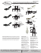
Switch Action (Normally Open, Normally Closed)
Vertical Models
Vertical mount models are shipped with normally open switch contacts
that close as the float rises toward the mounting threads. To reverse the
switch action, remove the float, rotate it end-for-end, and then replace it
back on the stem. The floats will be marked for Normal Open and Normal
Closed orientation.
Horizontal Models
Contacts in the horizontal models F6-HPS-11 (internally mounted), F6-
HPS-21 (externally mounted), and F6-HPS-31 (internally or externally
mounted) have indicating arrows on the wrench flat end of the switch to
confirm float alignment. When the indicating arrow points up and the
float is below the stem the switch is normally open and when the
indicating arrow points down and the float is above the stem the switch
is normally closed. The models F6-MHS and F6-MHS2 do not have an
indication arrow to show normally open or closed orientation. The
models F6-MHS and F6-MHS2 are normally open when the switch is
oriented so that the float is directly below the stem and normally closed
when the switch is oriented so that the float is directly above the stem.
Installation
Choose a location away from fill pipes, drains, or other areas where
turbulence or wave motion might occur. Turbulence will cause false
actuations and shorten contact life. Excess contaminants in fluid may
inhibit float operation and an occasional wipe-down may be necessary.
Care should be taken that switches are always operated within electrical
ratings.
Mounting
Install the vertical mount model in an appropriate 1/8” NPT fitting. The
vertical model mounts internally. It should be aligned within ±20° of
vertical, or select optional fittings for external mounting. Models F6-HPS-
11, F6-MHS and F6-MHS2 must be mounted internally, which means the
switch must be secured to the wall of the tank or vessel from the inside.
Install horizontal models F6-HPS-11 and F6-MHS in a M16 suitable size
hole and secure them with the nut provided. Models F6-HPS-21 and F6-
MHS2 require a horizontal 1/2˝ NPT fitting and can be fitted to the tank
or vessel from the outside. Models F6-HPS-31 and F6-MHS2 require a
horizontal 1/2˝ NPT fitting and can be mounted from the inside or outside
(internally or externally) of the tank or vessel.
MAINTENANCE
Upon final installation of the Series F6 Level Switches, no routine
maintenance is required. A periodic check of system calibration is
recommended. The Series F6 is not field serviceable and should be
returned if repair is needed (field repair should not be attempted and
may void warranty). Be sure to include a brief description of the problem
plus any relevant application notes. Contact customer service to receive
a return goods authorization number before shipping.
W.E. ANDERSON DIV., DWYER INSTRUMENTS, INC.
P.O. BOX 358 • MICHIGAN CITY, INDIANA 46360 U. S. A.
Phone: 219/879-8000 www.dwyer-inst.com
Fax: 219/872-9057 e-mail: info@dwyermail.com