F-FLMG SERIES FLMG MUNICIPAL/INDUSTRIAL MAGMETER INSTRUCTIONS
TABLE OF CONTENTS General Information General Information, Features ................................................................................................... Page 1 Specifications Specifications, Flow Range ............................................................................................................
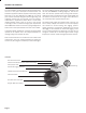
GENERAL INFORMATION The Series FLMG is a flanged electromagnetic flowmetersfor use in 4” to 10” pipe in municipal or industrial water and wastewater applications where propeller meters have typically been used in the past. Because the FLMG has no moving parts and has electrodes designed to discourage fouling, this magmeter performs well and requires much less frequent maintenance in applications where debris or sand would impede propeller meters. There is no rotor to stop turning or bearings to wear out.
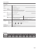
SPECIFICATIONS SPECIFICATIONS* Pipe Sizes 4”, 6”, 8”, 10” Flanges ANSI 150 lb drilling Pressure 150 psi (10.
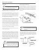
INSTALLATION and GROUNDING INSTALLATION EQUALIZATION AND GROUNDING Caution: These flow sensors are not recommended where installation fault may expose the flow sensor to boiler pressure and temperature. Maximum recommended temperature is 130˚ F. Positioning the Meter. These meters can be installed horizontally, vertically, and in any radial position. Straight Pipe Recommendations. As with most flow meters, the FLMG requires some straight pipe before and after the meter for best accuracy.
STRAIGHT PIPE RECOMMENDATIONS (X = diameter) 1X 2X Reduced Pipe FLMG Two Elbows In Plane 1X 2X FLMG Two Elbows, Out Of Plane 1X 2X FLMG 1X 5X Expanded Pipe FLMG 1X 5X Swirling Flow Propeller Meter FLMG 1X 5X Swirling Flow Partially Open Butterfly Valve FLMG Page 4
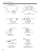
FULL PIPE RECOMMENDATIONS Recommended: Keeps pipe full at meter for accuracy FLMG FLMG Not Ideal: Allows air pockets to form at meter FLMG FLMG Recommended: Keeps pipe full at meter for accuracy Not Ideal: Post-valve cavitation can create air pocket FLMG FLMG Recommended: Allows air to bleed off Electrode moved from top by rotating meter FLMG Not Ideal: Air can be trapped Intermittent air bubbles miss electrode Electrodes free from sediment build-up Recommended: Improved accuracy results from
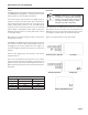
INPUTS/OUTPUTS and OPERATION Power. The FLMG operates on 8-32 VDC at 30 mA max external power (see WARNING in wiring diagrams). The display reads “P” when external power is in use (see illustration below). The Lithium battery pack installed in the FLMG serves as backup in the event of a power failure, when it will keep the meter operating without interruption for the duration of the outage.
CONNECTIONS DIAGRAMS (WMX101) The FLMG requires a power source of 8-32 VDC at 30 mA max (see WARNING). The power cable also serves as a pulse output if needed for remote reading, data logging, signal conversion, or telemetry.
TROUBLESHOOTING Problem Probable Cause Try...
WARRANTY/RETURN Refer to "Terms and Conditions of Sale" in our catalog or on our website. Contact customer service to receive a Returns Goods Authorization number before shipping your product back for repair. Be sure to include a brief description of the problem plus any relevant applciation notes. D w ye r I n s tru m e nts, I n c. • 1 0 2 I n di ana H ighway 212 • M i c higan Ci t y, IN 46360 • U SA ( P ) 2 1 9 . 8 7 9 . 8 8 6 8 • ( F ) 2 1 9 . 8 72.9057 • 1.800.872.9141 • www.dw yer- inst.