
Manual

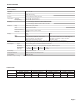


SPECIFICATIONS
Page 2
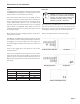
FLOW RANGE
4” 6” 8” 10”
Gal/Min Liter/Sec Gal/Min Liter/Sec Gal/Min Liter/Sec Gal/Min Liter/Sec
12 .75 32 2 60 3.8 95 6
500 31.5 1,200 75.7 2,200 138.8 3,500 220.8
Minimum
Maximum
SPECIFICATIONS*
*Specications subject to change.
4”, 6”, 8”, 10”
ANSI 150 lb drilling
150 psi (10.3 bar) working pressure
10˚ to 130˚ F (-12˚ to 54˚ C)
-40˚ to 158˚ F (-40˚ to 70˚ C)
+/- 1% of reading for ow between 10% to 100% of max ow
+/- 2% of reading for ow from cutoff to 10% of max ow
Welded steel, epoxy-coated
Dual durometer rubber
Diecast aluminum, powder-coated
316 SS
Rate
Total
5 8
Gallon/Minute, Liter/Minute, Liter/Second, Gallon, Gallon x 1000, Liter, Liter x 1000, Mega Liter,
Cubic Feet/Minute, Cubic Meter/Hour, Cubic Meter, Cubic Meter x 1000, Cubic Feet,
Million Gallon/Day, Mega Liter/Day Cubic Feet x 1000
7-32 Vdc at 30 mA max, with auxiliary battery for continuous operation during power failures
NOTE: Using an unregulated power supply >18 Vdc may damage the meter due to AC line input voltage uctuation
Current sinking pulse, opto-isolated, 30 Vdc at 10 mA max
High Frequency (default); 10 units/pulse; 100 units/pulse; 1000 units/pulse
4” 6” 8” 10”
16.362 6.307 3.344 2.150
>20 microSiemens/cm
Hardware/software, conductivity-based
NEMA 4X (IP66)
Pipe Sizes
Flanges
Pressure
Temperature Operating
Non-Operating
Accuracy
Materials Body
Liner
Electronics Housing
Electrodes
Display
Digits
Units
Power
Pulse Output Signal
Pulse Rates
High Frequency
(pulse/gal)
Conductivity
Empty Pipe Detection
Environmental