
Install Instructions

The Series V6 FLOTECT
®
Flow Switch is an inexpensive, explosion-proof flow
switch for use on air, water or other compatible gases and liquids. Three configu-
rations are available - 1. Factory installed in a tee. 2. With a trimmable vane for
field adjustment and installation in a suitable tee. 3. Low flow models with an inte-
gral tee and adjustable valve. All are available with an optional enclosure which is
UL and CSA listed, or Directive 2014/34/EU (ATEX) compliant for
2813 II 2 G Ex db IIC T6 Gb
Process Temp≤75°C or IECEx compliant for Ex db IIC T6 Gb Process Temp ≤
75°C.
Series V6 FLOTECT
®
Flow Switch
Specifications - Installation and Operating Instructions
Bulletin E-22
ELECTRICAL CONNECTIONS
Connect wire leads in accordance with local electrical codes and switch action
required. N.O. contacts will close and N.C. contacts will open when flow increases
to the actuation point. They will return to “normal” condition when flow decreases
to the deactuation point. Black = Common, Blue = Normally Open and Red =
Normally Closed.
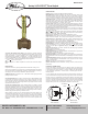
For units supplied with both internal ground and external bonding terminals, the
ground screw inside the housing must be used to ground the control. The external
bonding screw is for supplementary bonding when allowed or required by local
code. When external bonding conductor is required, conductor must be wrapped a
minimum of 180° about the external bonding screw. See below. Some CSA listed
models are furnished with a separate green ground wire. Such units must be
equipped with a junction box, not supplied but available on special order.
DWYER INSTRUMENTS, INC.
P.O. BOX 373 • MICHIGAN CITY, INDIANA 46360, U.S.A.
Phone: 219-879-8000 www.dwyer-inst.com
Fax: 219-872-9057 e-mail: info@dwyermail.com
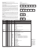
SPECIFICATIONS
Service: Gases or liquids compatible with wetted materials.
Wetted Materials: Standard V6 Models: Vane: 301 SS; Lower Body: brass or 303
SS; Magnet: ceramic; Other: 301, 302 SS; Tee: brass, iron, forged steel, or 304 SS.
V6 Low Flow Models: Lower Body: brass or 303 SS; Tee: brass or 304 SS; Magnet:
ceramic; O-ring: Buna-N standard, Fluoroelastomer optional; Other: 301, 302 SS.
Temperature Limits: -4 to 220°F (-20 to 105°C) Standard, MT high temperature
option 400°F (205°C) (MT not UL, CSA, ATEX, IECEx or KC) ATEX Compliant AT,
IECEx IEC Option and KC (KC Option), Ambient Temperature -4 to 167°F (-20 to
75°C) Process Temperature: -4 to 220°F (-20 to 105°C).
Pressure Limit: Brass lower body with no tee models 1000 psig (69 bar), 303 SS
lower body with no tee models 2000 psig (138 bar). Brass tee models 250 psi (17.2
bar), iron tee models 1000 psi (69 bar), forged and stainless steel tee models 2000
psi (138 bar), low flow models 1450 psi (100 bar).
Enclosure Rating: Weatherproof and Explosion-proof. Listed with UL and CSA for
Class I, Groups A, B, C and D; Class II, Groups E, F, and G. (Group A on stainless
steel body models only).
2813 II 2 G Ex db IIC T6 Gb Process Temp≤75°C Alternate Temperature
Class T5 Process Temp≤90°C, 115°C (T4) Process Temp ≤105°C consult factory.
EU-Type Certificate No.: KEMA 04ATEX2128.
ATEX Standards: EN 60079-0: 2011 + A11:2013; EN 60079-1: 2014.
IECEx Certified: For Ex db IIC T6 Gb Process Temp≤75°C Alternate Temperature
Class T5 Process Temp≤90°, 115°C (T4) Process Temp≤105°C consult factory.
IECEx Certificate of Conformity: IECEx DEK 11.0039; IECEx Standards: IEC
60079-0: 2011; IEC 60079-1: 2014; Korean Certified (KC) for: Ex d IIC T6 Gb
Process Temp≤75°C; KTL Certificate Number: 12-KB4BO-0091.
Switch Type: SPDT snap switch standard, DPDT snap switch optional.
Electrical Rating: UL models: 5 A @125/250 VAC. CSA, ATEX and IECEx models:
5 A @ 125/250 VAC (V~); 5 A res., 3 A ind. @ 30 VDC (V ). MV option: 0.1 A @
125 VAC (V~). MT option: 5 A @125/250 VAC (V~). [MT option not UL, CSA, ATEX
or IECEx].
Electrical Connections: UL models: 18 AWG, 18˝ (460 mm) long. ATEX/CSA
/IECEx models: terminal block.
Upper Body: Brass or 303 stainless steel.
Conduit Connections: 3/4˝ male NPT standard, 3/4˝ female NPT on junction box
models. M25 x 1.5 with BSPT option.
Process Connection: 1/2˝ male NPT on models without a tee.
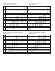
Mounting Orientation: Switch can be installed in any position but the actuation/de-
actuation flow rates in the charts are based on horizontal pipe runs and are nominal
values.
Set Point Adjustment: Standard V6 models none. Without tee models vane is trim-
mable. Low flow models are field adjustable in the range shown. See set point
charts on opposite page.
Weight: 2 to 6 lb (.9 to 2.7 kg) depending on construction.
Options not Shown: Custom calibration, bushings, PVC tee, reinforced vane,
DPDT relays.
INSTALLATION
Unpack and remove any packing material found inside lower housing or tee.
Switch can be installed in any position but the actuation/deactuation flow rates in
the charts are based on horizontal pipe runs and are nominal values. For more pre-
cise settings, units can be factory calibrated to specific flow rates.
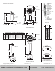
V6 Models with Tee are supplied in 1/2˝ - 2˝ NPT sizes. Install in piping with arrow
pointing in direction of flow.
V6 Low Flow Models have 1/2˝ NPT connections and are field adjustable. Install
in piping with arrow pointing in direction of flow. To adjust, loosen the four socket
head cap screws on bottom. The adjustment valve rotates 90° between “O” (open)
and “C” (closed). See flow charts for approximate ranges. Tighten screws once the
required flow rate has been set.
V6 with Field Trimmable Vane. These models enable the installer to choose
approximate actuation/deactuation points by trimming the full size vane at appro-
priate letter-designated marks on a removable template. Flows are defined in the
following charts. Note that the charts are based on either brass or cast iron reduc-
ing tees or stainless or forged steel straight tees with bushings where necessary.
Install in piping with arrow pointing in direction of flow.
When bushings are used, they must be back drilled to allow proper clearance for
unrestricted vane travel. Bore the I.D. to 13/16˝ (20 mm) on 1/2˝ x 3/4˝ bushings or
1˝ (25 mm) on larger bushings. The depth of the bore must leave internal threads
9/16˝ (14 mm) high for proper engagement between the lower housing of the
switch and the bushing. Check for proper vane travel and switch operation after
installation.
FRONT VIEW DETAIL SIDE VIEW DETAIL
CLAMP
SCREW
LOCKWASHER
CONDUCTOR