
Install Instructions
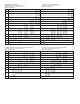

V6 With Tee
Cold Water - Factory Installed Tee
Approximate actuation/deactuation low Rates
GPM upper, M
3
/HR lower
Air-Factory Installed Tee
Approximate actuation/deactuation flow rates
SCFM upper, NM
3
/M lower
V6 Low Flow, Field Adjustable
Cold Water - Low Flow Models
Approximate actuation/deactuation flow rates
GPM upper, M
3
/HR lower
Air - Low Flow Models
Approximate actuation/deactuation flow rates
SCFM upper, NM
3
/M lower
1/2˝ NPT
1.5 1.0
0.34 0.23
3/4˝ NPT
2.0 1.25
0.45 0.28
1˝ NPT
3.0 1.75
0.68 0.40
1-1/4˝ NPT
4.0 3.0
0.91 0.68
1-1/2˝ NPT
6.0 5.0
1.36 1.14
2˝ NPT
10.0 8.5
2.27 1.93
1/2˝ NPT
6.5 5.0
.18 .14
3/4˝ NPT
10.0 8.0
.28 .23
1˝ NPT
14 12
.40 .34
1-1/4˝ NPT
21 18
.59 .51
1-1/2˝ NPT
33 30
.93 .85
2˝ NPT
43 36
1.19 1.02
Minimum
.04 .03
.009 .007
Maximum
.75 0.60
0.17 0.14
Minimum
.18 .15
.005 .004
Maximum
2.70 2.0
.08 .06
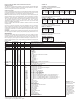
Example
Series
Construction
Body
Switch Type
Tee Connection
Size
Tee Type and
Material
Options
V6
V6
EP
EP
1
1
2
3
4
5
6
LF
1E
2E
3E
4E
5E
6E
LFE
B
B
S
O
AT
18
20
22
022A
31
AT
BUSH2
BUSH3
BUSH4
BUSH5
BUSH6
BUSH7
BUSH8
BUSH9
BUSH10
BUSH11
CSA
CV
FTR
GL
ID
IEC
JCTLH
KC
MT
MV
NN
ORFB
ORFS
PT
RV
ST
TBC
VIT
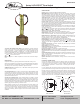
Series V6EPB-B-D-1-B-AT Flotect
®
Mini-Size Flow Switch, brass body, DPDT, 1/2"
brass tee, with ATEX approval.
Flotect
®
Mini-Size Flow Switch
Explosion Proof
Brass
Stainless Steel
DPDT
SPDT
1/2" NPT
3/4" NPT
1" NPT
1-1/4" NPT
1-1/2" NPT
2" NPT
Low Flow with 1/2" NPT Inlet and Outlet
1/2" BSPT ++
3/4" BSPT ++
1" BSPT ++
1-1/4" BSPT ++
1-1/2" BSPT ++
2" BSPT ++
Low Flow with 1/2" BSPT Inlet and Outlet ++
Brass
Stainless Steel
NO Tee with Field Trimmable Vane
0.018 Spring for Low Flow
.020 Spring for Low Flow
.022 Spring for Low Flow
.022 Spring for Low Flow with Alnico Magnet
.031 Spring for Low Flow
ATEX Approval
1/2" NPT x 3/4" NPT Bushing
1/2" NPT x 1" NPT Bushing
1/2" NPT x 1-1/4" NPT Bushing
1/2" NPT x 1-1/2" NPT Bushing
1/2" NPT x 2" NPT Bushing
1/2" BSPT x 3/4" BSPT Bushing, M25 X 1.5 Conduit Connection ++
1/2" BSPT x 1" BSPT Bushing, M25 X 1.5 Conduit Connection ++
1/2" BSPT x 1-1/4" BSPT Bushing, M25 X 1.5 Conduit Connection ++
1/2" BSPT x 1-1/2" BSPT Bushing, M25 X 1.5 Conduit Connection ++
1/2" BSPT x 2" BSPT Bushing, M25 X 1.5 Conduit Connection ++
CSA*
Custom Vane
Flow Test Report
Ground Lead*
Custom Nameplate
IECEx Approval
Junction Box with Left Side Conduit
Korean Certified*
High Temperature*
Gold Contacts
No Nameplate*
Brass Orifice
Stainless Steel Orifice
Paper Tag
Reinforced Vane
Stainless Steel Tag
Terminal Block Connector*
Flouroelstomer Seals
BB
BB
SS
EU-Type Certificate, IECEx and KC Installation Instructions:
Cable Connection
The cable entry device shall be certified in type of explosion protection flameproof
enclosure “d”, suitable for conditions of use and correctly installed. For Ta ≥ 65°C
cable and cable gland rated ≥ 90°C shall be used.
Conduit Connection
An Ex d certified sealing device such as a conduit seal with setting compound shall
be provided immediately to the entrance of the valve housing. For Ta ≥ 65°C wiring
and setting compound, in the conduit seal, rated ≥ 90°C shall be used.
Note: ATEX, IECEx and KC units only: The temperature class is determined by the
maximum ambient and or process temperature. Units are intended to be used in
ambient of -20°C≤ Tamb ≤75°C. Units may be used in process temperatures up to
105°C providing the enclosure and switch body temperature do not exceed 75°C.
The standard Temperature Class is T6 Process Temp ≤75°C. Alternate
Temperature Class of T5 Process Temp ≤90°C and 115°C (T4) Process Temp
≤105°C are available consult factory.
Refer to Certificate No: IECEx DEK 11.0039 for conditions of safe use for IECEx
compliant units.
All wiring, conduit and enclosures must meet applicable codes for hazardous
areas. Conduits and enclosures must be properly sealed. For outdoor or other
locations where temperatures vary widely, precautions should be taken to prevent
condensation inside switch or enclosure. Electrical components must be kept dry
at all times.
CAUTION: To prevent ignition of hazardous atmospheres, disconnect the device
from the supply circuit before opening. Keep assembly tightly closed when in use.
MAINTENANCE
Inspect and clean wetted parts at regular intervals. The cover should be in place
at all times to protect, the internal components from dirt, dust and weather and to
maintain hazardous location ratings. Disconnect device from the supply circuit
before opening to prevent ignition of hazardous atmosphere. Repairs to be con-
ducted by Dwyer Instruments, Inc. Units in need of repair should be returned to the
factory prepaid.
Attention: Units
without the “AT” suffix
are not Directive
2014/34/EU (ATEX)
compliant. These
units are not intend-
ed for use in poten-
tially hazardous
atmospheres in the
EU. These units may
be CE marked for
other Directives of
the EU.
D
D
S
*O p tions that do no have ATEX or IECEx
++ BSPT options not com patible with KC option