
Install Instructions

©Copyright 2019 Dwyer Instruments, Inc. Printed in U.S.A. 4/19 FR# 440866-00 Rev. 3
Series V8 Flotect
®
Flow Switch
Specications - Installation and Operating Instructions
Bulletin E-25
INSTALLATION
1. The Model V8 Flow Switch is intended for use in clean, compatible process media
free from scale, debris and other foreign matter which might collect on the vane and
impede its movement. Buildup from such materials will prevent proper operation.
2. Carefully unpack the switch being certain to remove any packing material which
might have become lodged between the switch housing and the vane assembly. Note
the pipe size indicators molded into the vane. By trimming at the mark corresponding
to the pipe size being used, approximate actuation/deactuation ows will be as shown
in the charts at right. These values apply to installations with a thred-o-let, branch
connection or plastic tting. If using standard 125-250 lb. bronze, iron or steel ttings,
trim the vane 0.125˝ above the mark. Due to variations in ttings and amount of thread
engagement, vane must be checked for proper operation.
3. The ow switch must be properly indexed during installation. The arrow on the side
must point in the direction of ow.
4. Use Teon
®
thread tape or other suitable pipe joint compound to seal the 1˝ NPT
mounting connection. Avoid excess sealant which could interfere with vane movement
and prevent proper operation. Do not exceed 50 ft/lbs (40 n/m) torque on the switch
housing. Damage can result.
5. Wire in accordance with local electrical codes. Lead wire colors are as follows:
Black - Common, Red - Normally Open, Blue - Normally Closed. Normal is the contact
condition with no ow in the system. Closed contacts open and open contacts close
when increasing ow reaches the actuation point.
6. Switch electrical components must be protected from moisture at all times. If
necessary, install a lightweight waterproof junction box over the 1/2˝ NPT threaded
stem. Do not place mechanical loading on the switch housing. Permanent damage can
occur. Use exible Romex sheathing or equivalent.
SPECIFICATIONS
Maximum Temperature: 212°F (100°C).
Maximum Pressure: 150 psig (10.3 bar).
Process Connection: 1˝ NPTM.
Conduit Connection: 1/2˝ male NPT, 1/2˝ female NPT on WP and WP2.
Switch Type: SPDT snap switch; MV option: SPDT gold contact snap switch.
Electrical Rating: 5 A @ 125/250 VAC. MV Option: 0.1 A @ 125 VAC.
Wire Leads: 18 AWG x 18 in (45.7 cm).
Overall Length: 9.375 in (23.8 cm).
Switch Body: Polyphenylene sulphide (PPS).
Wetted Materials: Polyphenylene sulphide, ceramic 8 magnet, 316 stainless steel.
Vane: Field trimmable.
Mounting Orientation: Actuation/deactuation ow rates are based on horizontal
pipe runs and are nominal values. Unit cannot be used with vertical down ow.
Weight: 4.5 oz (128 g).
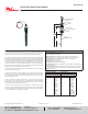
1.650 DIA. [42]
3 1/16
[78]
9 3/8
[238]
5 1/4
[134]
TRAVEL
1/2 NPTM
1 5/16 [34] OCTAGO
N
1 NPTM
FIELD
TRIMMABLE VANE
SWITCH BODY
[3] 18 AWG LEAD WIRES,
18 [460] LONG
Cold water Flow Rates Air Flow Rates
Approx. Actuation/Deactuation
GPM Upper, LPM Lower
Approx. Actuation/Deactuation
SCFM Upper, NM
3
/H Lower
Pipe Size Pipe Size
1˝
1-1/4˝
1-1/2˝
2˝
3˝
4˝
6˝
10.8/9.1
40.9/34.6
9.8/8.3
37.2/31.4
8.6/6.8
32.4/25.7
10.9/8.8
41.2/33.4
12.9.8.9
48.8/33.5
21.1/13.8
79.7/52.2
45/33
170.2/124.7
1˝
1-1/4˝
1-1/2˝
2˝
3˝
4˝
6˝
39/32.6
66.3/55.4
37.5/32.2
63.7/54.7
33.4/26.7
56.7/45.4
43/36.8
73.1/62.5
52.7/38.9
89.6/66
87.6/63.6
148.9/108.1
168.6/137.4
286.5/233.4
W.E. ANDERSON
P.O. BOX 373 • MICHIGAN CITY, INDIANA 46360, U.S.A.
Phone: 219/879-8000
Fax: 219/872-9057
www.dwyer-inst.com
e-mail: info@dwyermail.com
A DIVISION OF
DWYER INSTRUMENTS, INC.
By Dwyer