
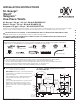
Installation Sheet

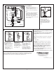

a. Close toilet supply valve and ush tank completely. Towel or sponge remaining water from tank and bowl.
b. Disconnect and remove supply line. NOTE: If replacing valve, first shut off main water supply!
c. Remove old mounting hardware, remove toilet and plug oor waste opening to prevent escaping sewer gases.
d. Remove closet bolts from ange and clean away old wax, putty, etc. from base area.
NOTE: Mounting surface must be clean and level before new toilet is installed!
SAVE FOR FUTURE USE
St. George 1.28 gpf / 4.8 Lpf - Model# D22000C101
Wyatt 1.28 gpf / 4.8 Lpf - Model# D22005C101
Seagram 1.28 gpf / 4.8 Lpf - Model# D22015F101
St. George
™
Wyatt
™
Seagram
™
One-Piece Toilets
INSTALLATION INSTRUCTIONS
Product names listed herein are trademarks of AS America, Inc.
© AS America, Inc. 2013
REMOVE OLD TOILET
1
CAUTION: PRODUCT IS FRAGILE. TO AVOID BREAKAGE AND POSSIBLE INJURY HANDLE WITH CARE!
NOTE: Pictures may not exactly define contour of china and components.
Thank you for selecting DXV by American Standard. To ensure this product is installed properly, please read these instructions carefully
before you begin. (Certain installations may require professional help.) Also be sure your installation conforms to local codes.
!
Most of the procedures require the use of common tools and materials, which are available from hardware and plumbing,
supply stores. It is essential that the tools and materials be on hand before work is begun.
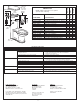
RECOMMENDED TOOLS AND MATERIALS
Adjustable Wrench GasketWax Ring
Regular Screwdriver
10'
Level Flexible Supply Tube
Closet Bolts
Putty Knife
Tape Measure
Hacksaw
Sealant
7302029-100 Rev. B
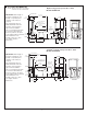
ROUGHING-IN DIMENSIONS:
NOTE: Distance from wall to closet flange
centerline must be as listed below:
St. George
™
1.28 gpf / 4.8 Lpf One-Piece Toilet
Model# D22000C101
IMPORTANT: Water supply on the wall is required at
3-3/4" (95mm) or 9" (299mm) from centerline of the
toilet (see rough-in).
First suggested position is hidden behind the toilet.
The geometry of the toilet gives space for this
installation.
The second suggested position is next to the toilet.
Between these two positions, the space for the
supply between wall and toilet is limited to 3-1/4"
(95mm). In this case, check your supply and hose
dimensions.
2a
C/L OF OUTLET
AND TOILET
MTG BOLTS
29-7/8"
(758 mm)
18-1/2"
(470 mm)
16-1/2"
(419 mm)
8-1/2"
(217 mm)
12"
(305 mm)
14-1/4"
(361 mm)
8-1/8"
(206 mm)
C/L OF SEAT POST
HOLES 5-1/2"
(140mm) CENTERS
FINISHED WALL
3-11/16"
(94 mm)
5/8"
(16 mm)
3-1/2"
(88 mm)
2-3/4"
(80 mm)
FINISHED
FLOOR
14-3/4"
(376 mm)
30-3/4"
(781 mm)
15"
(380 mm)
14"
(356 mm)
5-1/2"
(140 mm)
SUPPLY AS
REQUIRED
(position 2)
SUPPLY AS
REQUIRED
(position 1)
6"
(152 mm)
9"
(229mm)
3-3/4"
(95mm)
ALL INSTALLATION PROCEDURES MUST COMPLY IN STRICT ACCORDANCE WITH APPLICABLE LOCAL
PLUMBING AND BUILDING CODES
- 1 -