3-BURNER LP GAS GRILL Model #DGC310CNP/DGC310CNP-D #DGC310RNP/DGC310RNP-D #DGC310BNP/DGC310BNP-D #DGC310GNP/DGC310GNP-D Français XX Français p. p. 28 XX Español Españolp.p.55 ATTACH YOUR RECEIPT HERE Serial Number _____________________________ Purchase Date ______________________ Questions, problems, missing parts? Before returning to your retailer, call our customer service department at 1-877-447-4768, 8:30 a.m. – 4:30 p.m., CST, Monday – Friday or e-mail us at customerservice@ghpgroupinc.com.
TABLE OF CONTENTS Safety Information ...................................................................................................................... 3 Package Contents ...................................................................................................................... 5 Hardware Contents .................................................................................................................... 6 Preparation ...................................................................
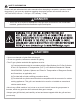
SAFETY INFORMATION Please read and understand this entire manual before attempting to assemble, operate or install the product. If you have any questions regarding the product, please call customer service at: 1-877-447-4768, 8:30 a.m. – 4:30 p.m., CST, Monday – Friday. DANGER • Do not use in an explosive atmosphere. Keep grill area clear and free from combustible materials, gasoline and other flammable vapors and liquids. CAUTION • Never use charcoal or lighter fluid with the grill.
SAFETY INFORMATION WARNING • Do not place the grill under overhead combustible construction or awnings. Minimum clearance from sides and back of unit to combustible construction, 36 inches (914.4mm) from sides and back. NOTE: The installation must conform with local codes or, in the absence of local codes, with either the National Fuel Gas Code, ANSI Z223.1/NFPA 54, Natural Gas and Propane Installation Code, CSA B149.1, or Propane Storage and Handling Code, B149.2.
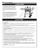
PACKAGE CONTENTS B A C D F E G J K F H I L R M N O P X Q S V T W U PART A B C D E F G H I J K L DESCRIPTION PART QUANTITY Warming Rack Hood and Grill Body Assembly Cooking Grate Heat Tent LP Gas Tank Heat Shield Side Table Assembly Grease Cup Cart Rear Upper Brace Assembly Cart Rear Lower Brace Assembly Left Rear Leg Assembly Cart Left Upper Brace Assembly Left Front Leg Assembly M N O P Q R S T U V W X 1 1 1 3 1 2 1 1 1 1 1 1 5 DESCRIPTION QUANTITY Cart Left Lower Brace Asse
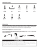
HARDWARE CONTENTS AA M6x12 Bolt Qty. 30 BB CC Wheel Wheel axle axle Wheel axle Wheel axle Cotter Cotterpin pin Cotter pin Qty. 2 Qty. 2 FF GG HH M6 Wingnut M6x18 Bolt M5 Wingnut Qty. 1 Qty. 2 Qty. 1 Cotter pin DD EE M4x12 Bolt M6x26 Bolt Qty. 6 Qty. 1 PREPARATION Before beginning assembly of product, make sure all parts are present. Compare parts with package contents list on previous page and hardware contents above.
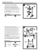
ASSEMBLY INSTRUCTIONS 1. Install left rear leg cap (T) onto left rear cart leg (J). Then install left front leg cap (U) onto left front cart leg(L) as illustrated. Use four M6x12 bolts (AA) to fasten the Cart Left Upper Brace Assembly (K) and Cart Left Lower Brace Assembly (M) onto Left Front Leg Assembly (L) and Left Rear Leg Assembly (J). DO NOT TIGHTEN BOLTS AT THIS TIME. 1 J L AA K M Hardware Used AA M6x12 Bolt x4 T U Wheel axle 2.
ASSEMBLY INSTRUCTIONS 3. Use four M4x12 bolts (DD) to assemble the cart front panel (R) between the Right Front Leg Assembly (O) and Left Front Leg Assembly (L). Note: The small edge of the front panel (R) should be on top. DO NOT TIGHTEN BOLTS AT THIS TIME. 3 R DD Hardware Used DD M4x12 Bolt x4 Cotter pin Wheel axle O 4. Use four M6x12 bolts (AA) Fasten the Cart Rear Upper Brace Assembly (H) onto Left Rear Leg Assembly (J) and Right Rear Leg Assembly (N).
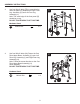
ASSEMBLY INSTRUCTIONS 5. Use one M6X26 bolts (EE) and one M6 wing 5 P nut (FF) to assemble the Tank Retention Bracket Q (P) to Tank Retention support Bracket (Q). Fasten Tank Retention Bracket (P) and Tank EE Retention support Bracket assembly (P+Q) in GG Wheel axle the Cart Right Upper Brace Assembly (S) by using two M6x18 bolts (GG). Cotter pin Wheel axle FF Cotter pin Hardware Used otter pin EE M6x26 Bolt x1 FF M6 Wingnut x1 GG 6.
ASSEMBLY INSTRUCTIONS 7. With the help of a friend, place hood and grill body assembly (B) on cart assembly. Use six M6x12 bolts (AA) to fasten. Note: When performing Step7, lift grill body from front and rear panels to avoid injury to hands and fingers. Once hood and grill body assembly (B) is placed correctly onto cart assembly, tighten ALL bolts securely from Steps 1, 2, 3, 4, and 6. 7 B AA Hardware Used AA M6x12 Bolt x6 Wheel axle 8.
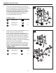
ASSEMBLY INSTRUCTIONS 9. Pre-assemble two M6x12 bolts (AA) onto the upper of left brace of hood and grill body assembly (B) and do not tighten them and make sure to leave a 5mm gap between the bolt and left brace of hood and grill body. Hang one of the Side Table Assembly (F) on the bolts and fasten the Side Table Assembly (F) with two M6x12 bolts (AA). Then tighten all the four bolts. 9 5mm F AA Hardware Used AA M6x12 Bolt x4 Cotter pin Wheel axle 10.
Wrong Wrong ASSEMBLY INSTRUCTIONS WARNING: IT IS VERY IMPORTANT TO CHECK AND ENSURE THAT EACH AND EVERY BURNER IS FULLY ENGAGED WITH THE ADJACENT VALVE ORIFICE BEFORE COMPLETING STEP 11. FAILURE TO DO SO MAY RESULT IN FIRE OR WARNING: IT POSSIBLY IS VER IMPORT ANT TO CHECK Y EXPLOSION, CAUSING SERIOUS AND ENSURE T REFER EACH AND Y BURNER INJURY OR THA DEATH. TO EVER MAINTENANCE IS FULLY ENGAGED WITH THE ADJACENT VALVE SECTION INSTRUCTIONS TO PROPERLY CHECK ORIFICE BEFORE COMPLETING STEP 1 1.
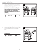
ASSEMBLY INSTRUCTIONS 13. Put one warming rack (A) in place. 13 A 14. Slide grease cup (G) onto tracks in the bottom of firebox as illustrated.
ASSEMBLY INSTRUCTIONS 15. Place gas cylinder (sold separately) upright into the notches of the tank support bracket on the bottom of right legs, orient the cylinder such that the valve opening faces the right side of the grill, and the hose is not kinked or damaged. Loose and slide down tank retention bracket over LP Gas cylinder collar ,then use the wing nut to secure tightly. Hand-tighten the hose/regulator coupling to the threaded valve of the LP gas cylinder.
OPERATION INSTRUCTIONS CHECKING FOR LEAKS After all connections are made, check all connections and fittings on the LP gas tank valve, gas hose and regulator for leaks with a water and soap solution. To prevent fire or explosion while testing for a leak: • Always perform leak test prior to lighting the grill. • Do not smoke while testing for a leak. • Always perform leak tests outdoors in a well-ventilated area. • Do not use any source of flame while testing for leaks.
REPLACEMENT PARTS LIST 2 1 3 4 6 5 7 9 11 10 12 8 13 14 15 16 18 17 21 19 23 20 22 24 25 26 23 27 29 28 33 35 30 31 32 38 34 36 39 37 41 42 26 40
REPLACEMENT PARTS LIST For replacement parts, call our customer service department at 1-877-447-4768, 8:30 a.m. – 4:30 p.m., CST, Monday – Friday.