Vertical Electric Analog Smoker MODEL #DGU505BAE / DGU505BAE-D Français p. 28 Español p. 56 FOR OUTDOOR USE ONLY Use only with Class A GFI (Ground Fault Interrupter) ATTACH YOUR RECEIPT HERE Serial Number ________________________________ Purchase Date _________________________________ Questions, problems, missing parts? Before returning to your retailer, call our customer service department at 1-877-447-4768, 8:00 a.m. – 4:30 p.m. CST, Monday – Friday or e-mail us at customerservice@ghpgroupinc.com.
DYNA-GLO®®VERTICAL GAS SMOKER DYNA-GLO VERTICAL ELECTRIC ANALOG SMOKER STOP! 2
TABLE OF CONTENTS Safety Information ...........................................................................................................................3 Package Contents ...........................................................................................................................8 Hardware Contents .........................................................................................................................9 Preparation Before Assembly .......................................
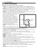
SAFETY INFORMATION IMPORTANT SAFEGUARDS READ ALL INSTRUCTIONS, PRIOR TO USING THIS SMOKER • DO NOT use this product for anything other than its intended purpose. It is NOT intended for commercial use. It is NOT intended to be installed or used in or on a recreational vehicle and/or boat. • DO NOT operate this smoker with a damaged cord or plug or after the smoker malfunctions, has been dropped, or is damaged in any manner.
SAFETY INFORMATION • DO NOT touch hot surfaces. Use handles or knobs. • To protect against electrical shock do not immerse cord, plugs, or thermostat control assembly in water or other liquid. • Close supervision is necessary when any appliance is used by or near children.
SAFETY INFORMATION Ground Fault Interrupter • Since 1971 the National Electric Code (NEC) has required Ground Fault Interrupter devices on all outdoor circuits. • If your residence was built before 1971, check with a qualified electrician to determine if a Ground Fault Interrupter protector exists. • Do not use this appliance if the circuit does not have Class A GFI protection. • Do not plug this appliance into an indoor circuit.
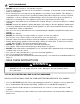
SAFETY INFORMATION WARNING To Avoid Serious Injury: • While cooking, the smoker must be on a level, stable, noncombustible surface in an area clear of combustible material, including long or dry grass. • The use of alcohol, prescription or nonprescription drugs may impair the user’s ability to properly assemble and safely operate this appliance. • DO NOT move the appliance while it is in use.
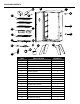
PACKAGE CONTENTS C B A Q F P O H G E I K R L N J M D PART A B C D E F G H I J K L M N O P Q R DESCRIPTION Smoker cabinet Side handle Door Door handle Wood chip access door handle Cooking grate Water bowl Wood chip box Wood chip box support Grease cup Heating element Thermostat control Temperature gauge Leg Door latch Door latch bracket Air outlet Thermostat shield 8 QUANTITY 1 2 1 1 1 3 1 1 1 1 1 1 1 4 1 1 1 1
HARDWARE CONTENTS AA BB CC DD ¼”-20 x ½” Screw #10-24 x 1” Screw #10-24 Screw #10-24 x ½” Screw Qty. 16 Qty. 2 Qty. 4 Qty. 9 PREPARATION BEFORE ASSEMBLY Before beginning assembly of product, make sure all parts are present. Compare parts with package contents list and hardware contents above. If any part is missing or damaged, do not attempt to assemble the product. Please read and understand this entire manual before attempting to assemble, operate or install the product.
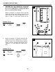
ASSEMBLY INSTRUCTIONS 1. CAUTION: This unit is HEAVY! Do not attempt the first 2 steps without assistance! Remove the door assembly (C) by opening and sliding the doors up and off the hinges. 1 C With the assistance of a helper, turn the smoker cabinet (A) upside down. Align the legs (N) on the front corners of the smoker cabinet (A). Secure with 8 ¼”-20 x ½” screws (AA). Tighten all bolts. Hardware Used AA ¼”-20 x ½” Screw x8 AA N A 2.
ASSEMBLY INSTRUCTIONS 3. Attach each of the side handles (B) to the smoker cabinet (A) using 4 ¼”-20 x ½” screws (AA) per side. 3 A B AA Hardware Used AA 4. ¼”-20 x ½” Screw x8 Attach the door latch (O) to the smoker cabinet (A) using 2 #10-24 x ½” screws (DD).
ASSEMBLY INSTRUCTIONS 5. Remove the pre-assembled screw from the wood chip access door handle (E) and install the handle (E) on the side access door of the smoker cabinet (A). 5 A E 6. Attach the heating element (K) to the smoker cabinet (A) using 2 #10-24 x ½” screws (DD) and 2 #10-24 Nuts (CC). 6 A CC K DD Hardware Used DD #10-24 x ½” Screw x2 CC #10-24 Nut x2 7. Attach the thermostat shield (R) to the smoker cabinet (A) using 2 10#-24*1/2'' screws (DD) .
ASSEMBLY INSTRUCTIONS 8. Hang the grease cup (J) to the bottom of the smoker cabinet (A). 8 A J 9. Place water bowl (G) and wood chip box (H) on the wood chip box support (I). Slide the wood chip box support (I) onto the bottom rails of the preinstalled wire supports.
ASSEMBLY INSTRUCTIONS 10. Insert cooking grates (F) on pre-installed wire supports inside the smoker cabinet (A). 10 F A 11. Firmly insert the thermostat control (L) into the external housing of the heating element (K).
ASSEMBLY INSTRUCTIONS 12. Attach the door handle (D) to the door (C) using 1 #10-24 x ½” screw (DD). 12 C D DD Hardware Used DD #10-24 x ½” Screw x1 13. Attach the door latch bracket (P) to the door (C) using 2 #10-24 x ½” screws (DD).
ASSEMBLY INSTRUCTIONS 14. Remove the pre-installed washer and nut from the temperature gauge (M) and insert the probe through the middle hole of the door (C). Secure with pre-assembled washer and nut. 14 M C 15. Attach the door (C) to the smoker cabinet (A).
REPLACEMENT PARTS LIST For replacement parts, call our customer service department at 1-877-447-4768, 8:00 a.m. - 4:30 p.m. CST, Monday - Friday or e-mail us at customerservice@ghpgroupinc.com.