
Use and Care Manual

8
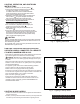
MAINTENANCE:
Always keep the heater area clear and free from combustible
materials, gasoline and other ammable vapors and liquids.
Keep the vent areas (slots in the bottom and the top at the front
of heater) clear at all times so combustion is ventilation air is not
obstructed. Visually inspect the pilot ame and burner periodical-
ly during use so combustion and ventilation air is not obstruct-
ed. The pilot ame should be blue in color (not yellow) and will
extend beyond the thermocouple. The ame will surround the
thermocouple just below the tip, see Figure 4. A slight yellow
ame may occur where the pilot ame and main burner ame
meet. The burner(s) should be bright orange (with a slight blue
color around the border, a red-orange haze that is visible on
the burner is acceptable) and without a noticeable ame. A blue
ame that rolls out at the top indicates an accumulation of dust,
lint or spider webs inside the main burner assembly. If the pilot
is yellow or the burner has a noticeable ame, cleaning may be
required. Use the following procedure to inspect main burner
assembly. It is necessary to periodically check the burner(s)
orice and burner venturi tube to make sure they are clear of
insects/nests or spider webs that may accumulate over time. It is
strongly recommended that these maintenance instructions be
performed annually. A clogged tube can lead to a re.
1 Allow heater to thoroughly cool before performing any main-
tenance.
2 Remove disposable 1 lb. cylinder(s) from heater or turn OFF
gas supply at remote cylinder valve, and disconnect hose
from heater.
3 Remove wire guard from heater by gently removing the four
screws attaching the wire guard.
4 And then remove the (3) acorn nuts and gently remove the
burner assembly exposing the burner venturi and pilot assem-
bly
5 Inspect interior of casing assembly for accumulation of dust,
lint or spider webs. If necessary, clean interior of casing
assembly with a vacuum cleaner or apply air pressure. Do not
damage any components within casing assembly when you
are cleaning.
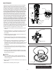
6 Inspect and clean main burner orice located at bottom of
burner venturi tube, by using a vacuum or apply air pressure
at orice opening.
7 Inspect and clean pilot (mounted to bracket) by using a vacu-
um or apply air pressure through the holes in the pilot indicat-
ed by the arrows in Figure 5.
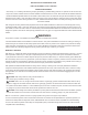
CAUTION:
Never use needles, wires, or similar cylindrical objects to
clean the pilot to avoid damaging the calibrated orice that
controls the gas ow.
8 Apply air pressure into burner assembly to remove dust, lint or
spider webs.
9 Reinstall burner assembly and wire guard.
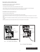
A
Burner Orifice
ODS Pilot Assy.
Wire Guard
Burner Assembly
Control
Knob
Door
Plastic Base
Assembly
Gas Train
Assembly
Upper Hinge
Lower Hinge
Pilot Flame
Pilot Air Hole
Burner Assembly
Venturi Tube
NEVER LEAVE THE HEATER
UNATTENDED WHILE BURNING!
Fig. 4 - Burner Orice Location
Fig. 5 - Pilot Assembly
Fig. 6 - Burner Assembly