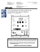
ITW Dynatec An Illinois Tool Works Company 31 Volunteer Drive Hendersonville, TN 37075 USA Telephone 615.824.3634 FAX 615.264.5222 ITW Dynatec GmbH Industiestrasse 28 D-40822 Mettmann, Germany Telephone 49.2104.915.0 FAX 49.210.2104.915.111 OPERATIONS & SERVICE MANUAL Manual 50 -05 Revised 1/23/04 ITW Dynatec K.K. Daiwashinagawa Bldg., 7-15 Konan, 3-Chome Minata-Ku, Tokoyo 108 Japan Telephone 81.3.3450.5901 FAX 81.3.3450.
Page ii Revised 1/99 ITW Dynatec An Illinois Tool Works Company Adhesive Application Solutions c.
ITW Dynatec c. 1999 TPC-2 TIMER Manual #50-56 Page iii Revised 1/99 TABLE OF CONTENTS CHAPTER 1:DESCRIPTION General Description ...................................................................................................................................... 1-1 Specifications................................................................................................................................................ 1-2 How to Use this Manual..........................................................
Page iv Revised 10/99 ITW Dynatec c. 1999 TPC-2 TIMER Manual #50-05 CHAPTER 5: TROUBLESHOOTING Controller Glues Every Other Sheet.............................................................................................................. 5-1 GlueLine Moves or Changes Length............................................................................................................. 5-1 Glue Applicators Will Not Activate......................................................................................
ITW Dynatec c. 1999 TPC-2 TIMER Manual #50-05 Page 1 - 1 Revised 11/04 Chapter 1 DESCRIPTION Description The ITW Dynatec TPC-2 Timer is a microprocessor-based electronic control system. It may be used in any process that requires the timed actuation of electrical output devices and has the ability to count those actuations and take varied actions based upon the count. It was specifically developed to control glue application valves used in adhesive systems.
Page 1 - 2 Revised 1/99 ITW Dynatec c. 1999 TPC-2 TIMER Manual #50-05 The TPC-2 possesses a PALLETISING facility that provides an easy means of applying glue to a specified number of objects, then passing (or skipping) a specified number of objects. The display continually updates itself to inform the operator of the current COUNT. A key-actuated system lock is provided on the Controller’s front panel. This lock prevents any unauthorized change to the programming when activated.
ITW Dynatec c. 1999 TPC-2 TIMER Manual #50-05 Page 2 - 1 Revised 8/99 Chapter 2 INSTALLATION The ITW Dynatec TPC-2 Timer is very easy to install and operate. It is highly recommended, however, that the entire contents of this manual be read before installation to become familiar with the many features of this equipment and to avoid potential safety hazards. WARNING: Line voltage is present at several places inside this Control Unit when it is connected to an AC power source.
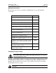
Page 2 - 2 Revised 1/04 ITW Dynatec c. 1999 TPC-2 TIMER Manual #50-05 Supplied Equipment The TPC-2 Control Kit is supplied with the following equipment. Please inventory these parts immediately upon unpacking the Control Kit to assure all items are present.
ITW Dynatec c.
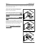
Page 2 - 4 Revised 11/04 ITW Dynatec c. 1999 TPC-2 TIMER Manual #50-05 The following steps should be employed to change the Control Unit’s operating voltage from the factory pre-set value: 1. Remove the 6 screws that secure the upper and lower portions of the Control Unit display panel using a cross-point screwdriver. 2. Remove the lower panel (the portion housing the power switch and fuse holder) from the case taking care not to strain the wires connected to the backside of the panel. 3.
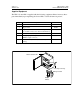
ITW Dynatec c. 1999 TPC-2 TIMER Manual #50-05 Page 2 - 5 Revised 8/99 Dimensions 1.19" 30mm 5.25” 133.4mm 11.56" 294mm 3.5" 89mm 3.5" 89mm 1.19" 30mm 0.27" 7mm 11.56" 294mm 10.81" 275mm .375" 10mm 9.75" 248mm .5" 13mm Locating the TPC-2 for Installation Mount the TPC-2 in a cool, dry, clean and well-ventilated area. Allow access space at the front and sides for operation and maintenance.
Page 2 - 6 Revised 12/99 ITW Dynatec c. 1999 TPC-2 TIMER Manual #50-05 Installing the TPC-2 and Accessories 1. Mount the TPC-2 Control Unit as close to the Trigger Input Device and the Glue Applicators as is possible. 2. Mount the Trigger Device and Glue Applicator(s) in the desired locations. Connect the Drive Output Cable(s) to the Glue Applicator(s). 3. Install the Automatic Tip Sealer(s) to the Glue Applicator(s) (cold glue systems) and connect the Drive Output Cable(s) to the Automatic Tip Sealer(s).
ITW Dynatec c. 1999 TPC-2 TIMER Manual #50-05 Page 2 - 7 Revised 11/04 230VAC Power Cord Wiring WIRE COLOR DESIGNATION Brown or Black Power (+) Blue or White Neutral (-) Green Ground CAUTION: Avoid the installation of input or output cords near or parallel to power lines from other machinery. The resulting electrical “noise” can produce adverse effects on the TPC-2 Control Unit which could result in unreliable operation.
Page 2 - 8 Revised 12/99 ITW Dynatec c. 1999 TPC-2 TIMER Manual #50-05 Important Note: The TPC-2 is usually connected to non-polarity-sensitive solenoids using the ITW Dynatec Output Kit (L21754) supplied as a part of the TPC-2 Control Unit Kit. As such, it is not important to which terminal the two wires of the Output Kit cables are connected. Polarity Sensitive solenoids, such as ITW Dynatec P/N 030A057 require attention to the manner in which the Output Kit wires are connected.
ITW Dynatec c. 1999 TPC-2 TIMER Manual #50-05 Page 3 - 1 Revised 1/99 Chapter 3 OPERATION & PROGRAMMING Start-Up Procedure 1. Open the latch on the right side of the TPC-2 Control Unit and swing open the lid. 2. Two keys for the Programming Security feature should be attached to the inside of the lid. Remove these keys and unwrap them. 3. Insert one of the keys into the lock on the Display Panel. Assure the key is in the UNLOCKED (key tab vertical) position. 4.
Page 3 - 2 Revised 1/99 ITW Dynatec c. 1999 TPC-2 TIMER Manual #50-05 Programming Conventions The TPC-2 employs the following programming conventions: 1. All CHANNEL modifications are performed on the Program displayed (Pr-1, -2, -3 or -4) when the MEMORY LED is illuminated. 2. Depressing the CHANNEL 1 or CHANNEL 2 buttons allows programming of the parameters for that channel of the selected Program (Pr-1, -2, -3 or -4). 3.
ITW Dynatec c. 1999 TPC-2 TIMER Manual #50-05 Page 3 - 3 Revised 1/99 System Status Lights There are four LED’s in the top right corner of the Display Panel that provide an indication of the current system status. These lights are described in further detail below: Drive 1 & Drive 2 These LED’s provide an indication of the current Drive Output activity.
Page 3 - 4 Revised 1/99 ITW Dynatec c. 1999 TPC-2 TIMER Manual #50-05 The A.T.S. output voltage is 48VDC at 5.4W for a 25ms duration. The output then drops to a holding voltage of 16VDC. The TPC-2 activates the A.T.S. Drive immediately upon receipt of Trigger Inputs. The Tip Sealing Device requires time to operate, the TPC-2 caters for this by allowing a 35ms dwell time from Trigger Input until the gluing program will function.
ITW Dynatec c. 1999 TPC-2 TIMER Manual #50-05 Page 3 - 5 Revised 1/99 PURGE Display Settings DISPLAY MEANING ===0 Activation of A.T.S. output only ===1 Activation of A.T.S. and DRIVE 1 outputs ===2 Activation of A.T.S. and DRIVE 2 outputs 3. Activation of the selected outputs occurs upon depressing the button on the Purge Control Unit (106078) and continues until the button is released.
Page 3 - 6 Revised 1/99 ITW Dynatec c. 1999 TPC-2 TIMER Manual #50-05 TIME RANGE Display Settings DISPLAY MEANING 0.001 Time Range Selection between 0.001 and 1.999 seconds 0.010 Time Range Selection between 0.01 and 19.99 seconds NOTE: Maximum time settings (i.e. 1.999 or 19.
ITW Dynatec c. 1999 TPC-2 TIMER Manual #50-05 Page 3 - 7 Revised 1/99 6. Rotate the VALUE knob until the desired “pass” quantity is selected. (Example: P.010 indicates that ten consecutive items will be passed). Start 7. Depress the SYSTEM button once. The display will now show either GLUE or PASS. 8. Rotate the VALUE knob until the desired value is displayed. The palletizing count will start with either the GLUE or the PASS count depending upon which value is selected for this parameter.
Page 3 - 8 Revised 1/99 ITW Dynatec c. 1999 TPC-2 TIMER Manual #50-05 volatile”, the settings are retained even when TPC-2 Control Unit input power is lost or the power switch is turned off. 1. Depress the SYSTEM button until the LED above the button is no longer illuminated and the green LED to the left of the MEMORY parameter is illuminated. 2. Rotate the VALUE knob until the desired Program (Pr – 1 through Pr – 4) is displayed. NOTES: a.
ITW Dynatec c. 1999 TPC-2 TIMER Manual #50-05 Page 3 - 9 Revised 1/99 2. Rotate the VALUE knob until the desired EVENT is selected. The table below indicates the meaning of each display setting.
Page 3 - 10 Revised 1/99 ITW Dynatec c. 1999 TPC-2 TIMER Manual #50-05 NOTES: a. The TPC-2 software forces minimum DELAY setting for EVENTS 2 through 4 that are dependent upon the DELAY and LINE values programmed into the previous EVENTs. b. The cumulative total time of all four EVENTs (DELAY and LINE) in a single Program may not exceed the maximum TIME RANGE value (either 1.999 or 19.99 seconds). c.
ITW Dynatec c. 1999 TPC-2 TIMER Manual #50-05 DELAY Page 3 - 11 Revised 1/99 LINE TRIGGER DEVICE GLUE VALVE DIRECTION OF TRAVEL Line The LINE parameter is the “glue” portion of each EVENT. 1. Depress the desired CHANNEL button until the LED to the left of LINE is illuminated. 2. Depress the DIGIT button the necessary number of times until the desired programming granularity is selected (the desired place-holder digit is flashing). 3. Rotate the VALUE knob until the desired LINE value is selected.
Page 3 - 12 Revised 1/99 ITW Dynatec c. 1999 TPC-2 TIMER Manual #50-05 2. Depress the DIGIT button the necessary number of times until the desired programming granularity is selected (the desired placeholder digit is flashing). 3. Rotate the VALUE knob until the desired GAP value is selected. 4. Displayed values range from 0000 to 0100. These numbers are expressed in milliseconds.
ITW Dynatec c. 1999 TPC-2 TIMER Manual #50-05 Page 3 - 13 Revised 1/99 NOTE: A GAP value greater than zero automatically changes a LINE to a series of “dots” unless STITCH is also programmed. Stitch STITCH is used when a series of intermittent glue patterns longer in duration than a “dot” is desired instead of a continuous LINE. The TPC-2 Control Unit divides LINE by the sum of GAP plus STITCH to determine the number of intervals.
Page 3 - 14 Revised 1/99 ITW Dynatec c. 1999 TPC-2 TIMER Manual #50-05 Spike Time The TPC-2 Control Unit offers a SPIKE voltage of 48VDC for a duration of from 000.1 to 025.5 milliseconds. The TPC-2 Drive output then settles to a 16VDC holding voltage for the duration of the LINE or STITCH. This feature is provided to enable quicker Glue Valve actuation when necessary. CAUTION: Assure the Glue Valve is designed to handle input voltages of 48VDC for short time periods prior to employing this feature.
ITW Dynatec c. 1999 TPC-2 TIMER Manual #50-05 Page 4 - 1 Revised 1/99 Chapter 4 PROGRAMMING EXAMPLES The following examples are provided to assist in better understanding the programming of the TPC-2 Control Unit. They assume that all components of the glue system (i.e. TPC-2 Control Unit, Trigger Device, Glue Applicators, Glue Delivery System, etc.) are properly installed.
Page 4 - 2 Revised 1/99 ITW Dynatec c. 1999 TPC-2 TIMER Manual #50-05 A Single EVENT Glue Pattern 90MS LINE 190MS DELAY TRIGGER DEVICE 10MS GLUE VALVE DIRECTION OF TRAVEL The following example places a series of dots on a substrate using a single glue applicator. 1. Turn ON the TPC-2 Control Unit. Depress the SYSTEM button until the LED to the left of TIME RANGE is illuminated. 2. Rotate the VALUE knob until 0.001 is displayed. 3.
ITW Dynatec c. 1999 TPC-2 TIMER Manual #50-05 Page 4 - 3 Revised 1/99 11. Use the same procedure as in Steps #6 through #9 above until 0090 (or 90ms) is displayed. 12. Depress the CHANNEL 1 button until the LED to the left of GAP is illuminated. 13. Use the DIGIT button and VALUE knob to set the display to 0010 (or 10ms). NOTE: Once a value is selected in GAP the LINE length is divided by the gap figure. The output from the TPC-2 Control Unit will be dots (i.e.
Page 4 - 4 Revised 1/99 ITW Dynatec c. 1999 TPC-2 TIMER Manual #50-05 20MS 80MS 60MS 10MS 60MS 20MS 60MS 10MS 10MS DIRECTION OF TRAVEL TRIGGER DEVICE GLUE VALVE 1. Turn ON the TPC-2 Control Unit. Depress the SYSTEM button until the LED to the left of TIME RANGE is illuminated. 2. Rotate the VALUE knob until 0.001 is displayed. 3. Depress the SYSTEM button until the LED to the left of MEMORY is illuminated. The LED above the SYSTEM button is now dim (not illuminated). 4.
ITW Dynatec c. 1999 TPC-2 TIMER Manual #50-05 Page 4 - 5 Revised 1/99 9. Rotate the VALUE knob until the second digit from the left is an 8. The display should now read 0080 (or 80ms). 10. Depress the CHANNEL 1 button until the LED to the left of LINE is illuminated. 11. Use the same procedure as in Steps #6 and #7 above until 0060 (or 60ms) is displayed. 12. Depress the CHANNEL 1 button until the LED to the left of GAP is illuminated. 13.
Page 4 - 6 Revised 1/99 ITW Dynatec c. 1999 TPC-2 TIMER Manual #50-05 NOTE: The SPIKE TIME parameter is not accessible when programming EVENT2 through EVENT4. Programming of SPIKE TIME for each CHANNEL occurs only during EVENT1. 27. Depress the CHANNEL 1 button until the LED to the left of EVENT is illuminated. 28. Rotate the VALUE knob until 3 is displayed. This indicates the programming of EVENT 3 of the selected Program. EVENT 3 is a solid glue line. 29.
ITW Dynatec c. 1999 TPC-2 TIMER Manual #50-05 Page 5 - 1 Revised 1/99 Chapter 5 TROUBLESHOOTING NOTE: Before any assumptions are made regarding an apparent fault, first check the input supply voltage. The voltage should be within ± 10% of the rated supply (i.e. 115VAC or 230VAC). Any variation from these parameters can result in controller malfunction.
Page 5 - 2 Revised 1/99 ITW Dynatec c. 1999 TPC-2 TIMER Manual #50-05 The glue system will not operate if the TPC-2 Control Unit is in the STOP mode (red LED above the RUN/STOP button is dim). 3. Is the Trigger Device operating properly? The TRIGGER Status LED in the upper right corner of the TPC-2 Control Unit Display Panel should illuminate for the duration of each TRIGGER input. Troubleshoot the Trigger Device and connection cable if the Status LED is not illuminating. 4.
ITW Dynatec c. 1999 TPC-2 TIMER Manual #50-05 Page 5 - 3 Revised 1/99 4. The problem is in either the Output Cable or Output Device (Glue Applicator or Automatic Tip Sealer) if the Status LED is green when the Trigger Device is activated with the Output Cable disconnected. Employ proper electrical troubleshooting techniques to identify the source of the problem in the cable or output device. Program Parameters Cannot Be Modified 1.
Page 5 - 4 Revised 1/99 c. 1999 ITW Dynatec ITW Dynatec c.
ITW Dynatec c. 1999 TPC-2 TIMER Manual #50-05 Page 6 - 1 Revised 2/99 Chapter 6 INSTALLATION & MAINTENANCE Replacement Parts Following is provided a listing of TPC-2 Control Unit replacement parts. The Item Number in the table refers to the equipment drawing following the table. Refer to Chapter 2 (Installation) for part numbers and descriptions for TPC-2 Control Kit equipment and optional accessories.
Page 6 - 2 Revised 10/99 ITW Dynatec c.
RED RED/WHITE 2 A-115V 1 A- 0V FILTER PCB BLACK/WHITE 4 B-115V J1 J4 BLACK 7 (0) 2 PE 1 N/L2 2 L1 3 5 WHITE BROWN BROWN WH ITE GR N/ YEL W HITE GRN /Y EL PW R SW W HITE BR OWN FU SE FU SE LOWE R F R ONT P ANEL ! "#"$ PINK PINK PINK 1 BLUE 3 T R IG 2 ! "#"$ RED ATS 6 BLACK 5 ! "# GRAY D RV 2 6 BLACK 5 ! "# U PPER F RONT PANEL BLACK D RV 1 6 BLACK 5 ! "# E N C L OS U R E W HITE C HASSI S GND GRN /YEL 8 1 GRN/YEL 4 3 2 J2 1 J3 11 W HITE 6 MA INS TR
-- 1 --
ITW Dynatec c. 1999 TPC-2 TIMER Manual #50-05 Page 2 - 5 Revised 11/04 Dimensions 1.19" 30mm 5.25” 133.4mm 11.56" 294mm 3.5" 89mm 3.5" 89mm 1.19" 30mm 0.27" 7mm 11.56" 294mm 10.81" 275mm .375" 10mm 9.75" 248mm .5" 13mm Locating the TPC-2 for Installation Mount the TPC-2 in a cool, dry, clean and well-ventilated area. Allow access space at the front and sides for operation and maintenance.
-- 3 --
-- 4 --
-- 1 --