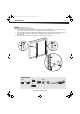
DX-DRTVL103_12-0662_MAN_V3_English.fm Page 1 Tuesday, June 19, 2012 12:32 PM ASSE M B LY I N S TRU C T I O N S DX-DRTVL103 Large Low Profile Wall Mount with Optional -5° Tilt For wood-stud, concrete-wall, or concrete-bloack installation Safety information and specifications...........................................2 TVs the wall mount fits ........................3 Tools needed ...........................................3 Parts ............................................................4 Hardware......
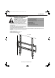
DX-DRTVL103_12-0662_MAN_V3_English.fm Page 2 Tuesday, June 19, 2012 12:32 PM 2 DX-DRTVL103 Safety information and specifications IMPORTANT SAFETY INSTRUCTIONS SAVE THESE INSTRUCTIONS Maximum weight: 70 lbs. (31.7 kg) CAUTION: Do not use this product for any Screen size: 26" to 52" diagonal purpose not explicitly specified by Dynex. Overall dimensions (W × H): 21.77" x 16.54" (553 x 420 mm) Improper installation may cause property Wall-mount weight: 5 lb (2.26 kg) damage or personal injury.
DX-DRTVL103_12-0662_MAN_V3_English.fm Page 3 Tuesday, June 19, 2012 12:32 PM DX-DRTVL103 3 TVs the wall mount fits The wall mount fits TVs with M4, M5, M6, or M8 screw holes that are the following distances apart: 15.81" (401.5 mm) vertical distance 1.375" to 15.
DX-DRTVL103_12-0662_MAN_V3_English.
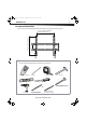
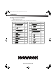
DX-DRTVL103_12-0662_MAN_V3_English.fm Page 5 Tuesday, June 19, 2012 12:32 PM DX-DRTVL103 5 Hardware Package contents: hardware Note: Not all hardware will be used. Make sure you have all the hardware necessary to assemble your new wall mount: Label Hardware Qty. 04 Label 13 4 5/16" × 2 3/4" lag bolt (7.9 mm × 69.9 mm) 05 5/16" (7.9 mm) washer 09 10 11 12 M8 × 16 mm screw Qty.
DX-DRTVL103_12-0662_MAN_V3_English.fm Page 6 Tuesday, June 19, 2012 12:32 PM 6 DX-DRTVL103 Step 1: Adjust the tilt Assembly instructions Note: The tilt on the left TV bracket (02) and right TV bracket (03) must be the same. 1 2 3 Use a Phillips screwdriver to remove the two screws (S) from the outside edges of each TV bracket (02 and 03). To tilt the TV forward by 5°, push the tilt brackets on the left TV bracket (02) and right TV bracket (03) down.
DX-DRTVL103_12-0662_MAN_V3_English.fm Page 7 Tuesday, June 19, 2012 12:32 PM DX-DRTVL103 7 Step 2: Determine whether your TV has a flat back or an irregular or obstructed back 1 2 3 Carefully place your TV screen face-down on a cushioned, clean surface to protect the screen from damages and scratches. If your TV has a table-top stand attached, remove the stand. See the documentation that came with your TV for instructions. Align the screw holes in the brackets with the mounting screw holes on your TV.
DX-DRTVL103_12-0662_MAN_V3_English.fm Page 8 Tuesday, June 19, 2012 12:32 PM 8 DX-DRTVL103 Step 3: Select screws and spacers 1 Select the hardware for your TV (screws, washers, and spacers). See the documentation that came with your TV for screw length and diameter.
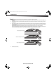
DX-DRTVL103_12-0662_MAN_V3_English.fm Page 9 Tuesday, June 19, 2012 12:32 PM DX-DRTVL103 9 Step 4: Install the TV brackets Option 1: Installing for a TV with a flat back 1 2 3 Align the holes you noted on the left TV bracket (02) and right TV bracket (03) with the screw holes on the back of your TV. The brackets are marked “R” for the right bracket and “L” for the left bracket.
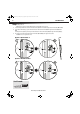
DX-DRTVL103_12-0662_MAN_V3_English.fm Page 10 Tuesday, June 19, 2012 12:32 PM 10 DX-DRTVL103 Step 4: Install the TV brackets (continued) Option 2: Installing for a TV with an irregular or obstructed back 1 2 3 4 5 Place M4/M5 spacers (19) or M6/M8 spacers (20) over the mounting holes in the back of your TV. If you are using M4 or M5 screws, place M4/M5 washers (17) over the spacers. Align the holes you noted on the left TV bracket (02) and right TV bracket (03) with the spacers.
DX-DRTVL103_12-0662_MAN_V3_English.fm Page 11 Tuesday, June 19, 2012 12:32 PM DX-DRTVL103 11 Step 5: Determine the wall-mount location. Note: For help with determining where you need to drill screw holes, use the HeightFinder™ Installation Assistant at: http://mf1.bestbuy.selectionassistant.com/index.php/heightfinder The center of your TV will match the center of the wall plate (01).
DX-DRTVL103_12-0662_MAN_V3_English.fm Page 12 Tuesday, June 19, 2012 12:32 PM 12 DX-DRTVL103 Step 6: Mount the wall plate Note: Any material covering the wall (such as sheetrock) must not exceed 5/8" (16 mm). Option 1: Mounting on a wood-stud wall 1 2 3 4 Locate the studs. Verify the center of the stud with an edge-to-edge stud finder. At the wall height you determined in the previous step, align the wall plate (01) against the wall and make sure that it is level.
DX-DRTVL103_12-0662_MAN_V3_English.fm Page 13 Tuesday, June 19, 2012 12:32 PM DX-DRTVL103 13 Step 6: Mount the wall plate (continued) Note: Any material covering the wall (such as sheetrock) must not exceed 5/8" (16 mm). Option 2: Mounting on a solid concrete or concrete block wall 1 2 3 4 Level the wall plate (01) and mark the hole locations. Drill pilot holes to a depth of 3" (75 mm) using a 3/8 in. (10 mm) diameter masonry drill bit.
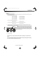
DX-DRTVL103_12-0662_MAN_V3_English.fm Page 14 Tuesday, June 19, 2012 12:32 PM 14 DX-DRTVL103 Step 7: Mount the TV on the wall plate Lower the TV onto the wall plate (01) making sure that the hooks on the top of the left and right TV brackets (02 and 03) slide over the top of the wall plate and the hooks on the bottom of the TV brackets slide under the bottom of the wall plate. Make sure that the TV is securely attached to the wall plate. 03 01 The TV is heavy. You will need assistance with this step.
DX-DRTVL103_12-0662_MAN_V3_English.fm Page 15 Tuesday, June 19, 2012 12:32 PM DX-DRTVL103 15 Removing the TV from the wall plate Simultaneously pull down on the two release cords on the TV brackets (02 and 03), then lift the TV up and away from the wall plate. For customer service, call: 800-305-2204 (U.S.
DX-DRTVL103_12-0662_MAN_V3_English.fm Page 16 Tuesday, June 19, 2012 12:32 PM www.dynexproducts.com (800) 305-2204 Distributed by Best Buy Purchasing, LLC 7601 Penn Ave. South, Richfield, MN 55423 U.S.A. © 2011 BBY Solutions, Inc. All rights reserved. DYNEX is a trademark of BBY Solutions, Inc. Registered in some countries. All other products and brand names are trademarks of their respective owners.