INSTRUCTION MANUAL for Installing E-GLIDE LADDER HARDWARE EG.
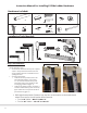
E B A A F C B Hardware Included: H D A A AA E x1 x2 x2 x28 B E Bx2 M5x18 Bx2B D x28 x1 GD D D D H C x2 x2 x2 M6x30 x1 x2 x2 x2x2 x1 x4 G x2 x2 x2 x2 x7 x2 x4 x4 x4 x7 x1 x1 E x14 x2 x28 M5x18 x1 x1 x1 x1x1 x2 M6x30 (x1) 3mm x7 x7 x7 x28 (x1) x283mm x28 x28 x1 5/16” Drill Bit x7 C (x1) 2mm 4mm x1 x1 x1x1 (x1) x7 3mm x1 x4x1 TOOLS REQUIRED G H Tools Needed: G G H HH GInstallation C H x1 x1 F x1 F x4 x7 x4 x4 x4 x14 x4 x4x4 x7 FFF x2 x2 x2 M5x18 M5x18 (x1)
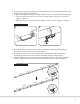
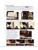
allation 2. Using a good quality level, lightly score a level pencil line on the headerboard where the bracket screw will be fastened into. 3. To splice rails together using the E-Glide splice kit (EG.41) complete the following steps: • Slide the splice half-way into one of the rails and tighten down the 2 set screws (figure 3, image 1) • Slide the other rail over the splice and tighten those set screws (figure 3, image 2) Figure 3 2 1 Installation 2 2mm 2 1 4.
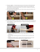
Step 2: Ladder Assembly (if applicable) If the ladder is Unfinished: It is recommended that the ladder side rails and steps are sanded slightly with a 220-grit sandpaper just prior to applying the finish (stain, paint, clear coat sealer, etc.). We recommend finishing the ladder before assembly. Before applying the finish, protect the insides of the dados and the ends of the steps with a quality painter’s tape.
. Using the supplied 1 1/4” washer-head screws, secure the step to the side rail through the predrilled holes on the side rails (for aesthetic purposes, don’t over tighten the screws which can crack the wood around the screw head). Assemble the remaining steps in the same manner (figure 9). 6. Once all the steps are assembled onto one of the side rails, position the side rail on its side with the steps pointing up. Figure 9 7.
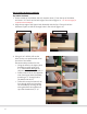
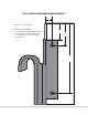
Step 3 Ladder Hardware Installation Top Ladder Hardware 1. On the outside of each ladder side rail, measure down 2” from the top of the ladder and draw a 11/2” line from the back edge of the side rail (figure 14 - see the next page for complete measurements). 2. Align the top edge of the Upper Hook Assembly with the line. Clamp or hold the hardware in place to drill the through holes in the side rail (figure 15). Figure 14 3.
TOP LADDER HARDWARE MEASUREMENTS 7/8” 2” down from top of ladder Fastener Hole Placement • 7/8” in from back edge of the side rail • 2 5/8” and 7 7/8” down from the top of the ladder to center of hole for the fastener 2” 2 5/8” 7 7/8” 7
Bottom Ladder Hardware 1. Mark a line on the bottom of each side rail 11/2” in from the front edge (figure 16). 2. Line up the Bottom Wheel Housing to the line drawn on the bottom of the side rail of the ladder using the “U” bracket portion of the housing. Verify that the bracket is flush with the bottom of the ladder. Because of the 12-degree angle of the bottom of the ladder this will align the housing diagonally across the ladder side rail (figure 17). Figure 16 Figure 17 1 1/2” 1 1/2” 3.
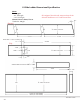
E-GLIDE HARDWARE MEASUREMENTS 1 3/4” 4 1/4” 1 3/4” 2” 6 1/2” 8” 13/16” 5 3/4” Upper Hook Measurements • Length - 4 1/4” • Width - 1 3/4” • Height - 6 1/2” Bottom Wheel Measurements • Length - 5 3/4” • Width - 1 3/4” • Height - 8” 2 5/8” 48” 9/16” 5/8” 1 15/16” 1 1/4” Rail Measurements • Length - 48” • Diameter - 1 1/4” Splice Measurements • Length - 2 5/8” • Width - 9/16” • Height - 5/8” 1/8” End Stop • Width - 1 15/16” • Diameter - 1/8” 1 1/4” 1 13/16” Upper Hook Measurements • Height - 1
E-Glide Ladder Dimensional Specification Notes: Two Lengths - 92” OA length - 107” OA length Material: Select or Better, Flat cut Sanded to 180 grit (Bottom) Notes: Two Lengt - 92” OA All 4 edges of the side rails, steps, and top of the - 107” OA side rails shall have a 1/4” radius round over. Material: Se Sanded to (Bottom) 12° 1/4” radius round over 10.750 10.625 Dado ..805 +/- .005 x .25 deep Dado ..805 +/- .005 x .25 deep variable 12° (Top) 12° (Top) .210D. .210D. .350D. 1.
Application Photos of E-Glide Ladders 11
REV. 8.13.