Elektro-Automatik Betriebsanleitung PSI 9000 DT DC-Labornetzgerät Doc ID: PSI9DTDE Revision: 01 Date: 08/2016
PSI 9000 DT Serie INHALT 1 ALLGEMEINES 1.1 1.1.1 1.1.2 1.1.3 1.1.4 1.2 1.3 1.4 1.5 1.6 1.7 1.7.1 1.7.2 1.7.3 1.7.4 1.7.5 1.8 1.8.1 1.8.2 1.8.3 1.8.4 1.9 1.9.1 1.9.2 1.9.3 1.9.4 1.9.5 1.9.6 1.9.7 1.9.8 1.9.9 2 Zu diesem Dokument.....................................5 Aufbewahrung und Verwendung....................5 Urheberschutz (Copyright).............................5 Geltungsbereich..............................................5 Symbolerläuterungen.....................................
PSI 9000 DT Serie 4 INSTANDHALTUNG & WARTUNG 5 SERVICE & SUPPORT 4.1 4.2 4.2.1 4.2.2 4.3 4.3.1 4.3.2 4.3.3 4.4 5.1 5.2 Seite 4 Wartung / Reinigung.....................................74 Fehlersuche / Fehlerdiagnose / Reparatur..74 Defekte Netzsicherung tauschen.................74 Aktualisierung der Firmwares.......................74 Nachjustierung (Kalibrierung).......................75 Einleitung.......................................................75 Vorbereitung..................................
PSI 9000 DT Serie 1. Allgemeines 1.1 Zu diesem Dokument 1.1.1 Aufbewahrung und Verwendung Dieses Dokument ist für den späteren Gebrauch und stets in der Nähe des Gerätes aufzubewahren und dient zur Erläuterung des Gebrauchs des Gerätes. Bei Standortveränderung und/oder Benutzerwechsel ist dieses Dokument mitzuliefern und bestimmungsgemäß anzubringen bzw. zu lagern. 1.1.
PSI 9000 DT Serie 1.4 Entsorgung des Gerätes 1.5 Produktschlüssel Ein Gerät, das zur Entsorgung vorgesehen ist, muß laut europaweit geltenden Gesetzen und Verordnungen (ElektroG, WEEE) vom Hersteller zurückgenommen und entsorgt werden, sofern der Betreiber des Gerätes oder ein von ihm Beauftragter das nicht selbst erledigt.
PSI 9000 DT Serie 1.7 Sicherheit 1.7.1 Sicherheitshinweise Lebensgefahr - Gefährliche Spannung • Beim Betrieb elektrischer Geräte stehen zwangsweise bestimmte Teile unter teils gefährlicher Spannung, mit Ausnahme der 40 V-Modelle gemäß SELV.
PSI 9000 DT Serie 1.7.2 Verantwortung des Bedieners Das Gerät befindet sich im gewerblichen Einsatz. Das Personal unterliegt daher den gesetzlichen Pflichten zur Arbeitssicherheit. Neben den Warn- und Sicherheitshinweisen in dieser Anleitung müssen die für den Einsatzbereich gültigen Sicherheits-, Unfallverhütungs- und Umweltschutzvorschriften eingehalten werden. Insbesondere gilt, daß die das Gerät bedienenden Personen: • sich über die geltenden Arbeitsschutzbestimmungen informieren.
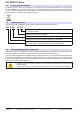
PSI 9000 DT Serie 1.7.5 Alarmsignale Das Gerät bietet diverse Möglichkeiten der Signalisierung von Alarmsituationen, jedoch nicht von Gefahrensituationen. Die Signalisierung kann optisch (auf der Anzeige als Text), akustisch (Piezosummer) oder elektronisch (Pin/Meldeausgang an einer analogen Schnittstelle) erfolgen. Alle diese Alarme bewirken die Abschaltung des DC-Ausgangs.
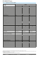
PSI 9000 DT Serie 1.8.3 Spezifische technische Daten Modell 320 W PSI 9040-20 DT PSI 9080-10 DT PSI 9200-04 DT Netzspannung 90...264 V AC 90...264 V AC 90...
PSI 9000 DT Serie Modell 320 W PSI 9040-20 DT PSI 9080-10 DT PSI 9200-04 DT Leistungsregelung Anzeige: Einstellauflösung Siehe Abschnitt „1.9.5.4. Auflösung der Anzeigewerte“ Anzeige: Genauigkeit (2 ≤ 0,8% PNenn ≤ 0,8% PNenn ≤ 0,8% PNenn Wirkungsgrad ~ 92% ~ 92% ~ 93% Einstellbereich 0,1...80 Ω 0,1...160 Ω 0,6...960 Ω Genauigkeit (1 (bei 23 ± 5°C) ≤ 2% vom Widerstandsbereich ± 0,3% vom Strombereich Anzeige: Einstellauflösung Siehe Abschnitt „1.9.5.4.
PSI 9000 DT Serie Modell 640 W PSI 9040-40 DT PSI 9080-20 DT PSI 9200-10 DT Netzspannung 90...264 V AC 90...264 V AC 90...264 V AC Netzanschluß 1ph,N,PE 1ph,N,PE 1ph,N,PE Netzfrequenz 45-65 Hz 45-65 Hz 45-65 Hz Netzsicherung MT 8 A MT 8 A MT 8 A Ableitstrom < 3,5 mA < 3,5 mA < 3,5 mA Leistungsfaktor ~ 0,99 ~ 0,99 ~ 0,99 Maximale Spannung UNenn 40 V 80 V 200 V Maximaler Strom INenn 40 A 20 A 10 A Maximale Leistung PNenn 640 W 640 W 640 W Überspannungsschutzbereich 0.
PSI 9000 DT Serie Modell 640 W PSI 9040-40 DT PSI 9080-20 DT PSI 9200-10 DT Leistungsregelung Anzeige: Einstellauflösung Siehe Abschnitt „1.9.5.4. Auflösung der Anzeigewerte“ Anzeige: Genauigkeit (2 ≤ 0,8% PNenn ≤ 0,8% PNenn ≤ 0,8% PNenn Wirkungsgrad ~ 92% ~ 92% ~ 93% Einstellbereich 0,1...40 Ω 0,1...80 Ω 0,6...480 Ω Genauigkeit (1 (bei 23 ± 5°C) ≤ 2% vom Widerstandsbereich ± 0,3% vom Strombereich Anzeige: Einstellauflösung Siehe Abschnitt „1.9.5.4.
PSI 9000 DT Serie Modell 1000 W PSI 9040-40 DT PSI 9080-40 DT PSI 9200-15 DT Netzspannung 90...264 V AC 90...264 V AC 90...
PSI 9000 DT Serie Modell 1000 W PSI 9040-40 DT PSI 9080-40 DT PSI 9200-15 DT Leistungsregelung Anzeige: Einstellauflösung Siehe Abschnitt „1.9.5.4. Auflösung der Anzeigewerte“ Anzeige: Genauigkeit (2 ≤ 0,8% PNenn ≤ 0,8% PNenn ≤ 0,8% PNenn Wirkungsgrad ~ 92% ~ 92% ~ 92% Einstellbereich 0,05...30 Ω 0,05...60 Ω 0,3...360 Ω Genauigkeit (1 (bei 23 ± 5°C) ≤ 2% vom Widerstandsbereich ± 0,3% vom Strombereich Anzeige: Einstellauflösung Siehe Abschnitt „1.9.5.4.
PSI 9000 DT Serie Modell 1000 W PSI 9360-10 DT PSI 9500-06 DT PSI 9750-04 DT Netzspannung 90...264 V AC 90...264 V AC 90...
PSI 9000 DT Serie Modell 1000 W PSI 9360-10 DT PSI 9500-06 DT PSI 9750-04 DT Leistungsregelung Anzeige: Einstellauflösung Siehe Abschnitt „1.9.5.4. Auflösung der Anzeigewerte“ Anzeige: Genauigkeit (2 ≤ 0,8% PNenn ≤ 0,8% PNenn ≤ 0,8% PNenn Wirkungsgrad ~ 93% ~ 93% ~ 93% Einstellbereich 0,8...1080 Ω 2...2250 Ω 4...5625 Ω Genauigkeit (1 (bei 23 ± 5°C) ≤ 2% vom Widerstandsbereich ± 0,3% vom Strombereich Anzeige: Einstellauflösung Siehe Abschnitt „1.9.5.4.
PSI 9000 DT Serie Modell 1500 W PSI 9040-60 DT PSI 9080-60 DT PSI 9200-25 DT Netzspannung ohne Derating 150...264 V AC 150...264 V AC 150...264 V AC Netzspannung mit Derating 90...150 V AC 90...150 V AC 90...
PSI 9000 DT Serie Modell 1500 W PSI 9040-60 DT PSI 9080-60 DT PSI 9200-25 DT Leistungsregelung Anzeige: Einstellauflösung Siehe Abschnitt „1.9.5.4. Auflösung der Anzeigewerte“ Anzeige: Genauigkeit (2 ≤ 0,8% PNenn ≤ 0,8% PNenn ≤ 0,8% PNenn Wirkungsgrad ~ 92% ~ 92% ~ 92% Einstellbereich 0,05...20 Ω 0,05...40 Ω 0,3...240 Ω Genauigkeit (1 (bei 23 ± 5°C) ≤ 2% vom Widerstandsbereich ± 0,3% vom Strombereich Anzeige: Einstellauflösung Siehe Abschnitt „1.9.5.4.
PSI 9000 DT Serie Modell 1500 W PSI 9360-15 DT PSI 9500-10 DT PSI 9750-06 DT Netzspannung ohne Derating 150...264 V AC 150...264 V AC 150...264 V AC Netzspannung mit Derating 90...150 V AC 90...150 V AC 90...
PSI 9000 DT Serie Modell 1500 W PSI 9360-15 DT PSI 9500-10 DT PSI 9750-06 DT Leistungsregelung Anzeige: Einstellauflösung Siehe Abschnitt „1.9.5.4. Auflösung der Anzeigewerte“ Anzeige: Genauigkeit (2 ≤ 0,8% PNenn ≤ 0,8% PNenn ≤ 0,8% PNenn Wirkungsgrad ~ 93% ~ 93% ~ 93% Einstellbereich 0,8...720 Ω 2...1500 Ω 4...3750 Ω Genauigkeit (1 (bei 23 ± 5°C) ≤ 2% vom Widerstandsbereich ± 0,3% vom Strombereich Anzeige: Einstellauflösung Siehe Abschnitt „1.9.5.4.
PSI 9000 DT Serie 1.8.4 Ansichten Bild 1 - Vorderseite (Tragegriff 90° nach unten) Bild 2 - Rückseite (Ansicht von 1000 W / 1500 W-Modellen) A - Netzschalter B - Bedienteil C - USB-Anschluß D - DC-Ausgang E - Fernfühlungs-Anschluß Seite 22 EA Elektro-Automatik GmbH Helmholtzstr. 31-33 • 41747 Viersen F - Steuerungsschnittstellen (digital, analog) G - Lüftungsaustritt H - Netzsicherung J - Netzanschluß Telefon: 02162 / 3785-0 Telefax: 02162 / 16230 www.elektroautomatik.de ea1974@elektroautomatik.
PSI 9000 DT Serie Bild 3 - Seitenansicht von links, liegend Bild 4 - Ansicht von oben (320 W & 640 W-Modelle) EA Elektro-Automatik GmbH Helmholtzstr. 31-33 • 41747 Viersen Telefon: 02162 / 3785-0 Telefax: 02162 / 16230 www.elektroautomatik.de ea1974@elektroautomatik.
PSI 9000 DT Serie Bild 5 - Ansicht von oben (1000 W & 1500 W-Modelle) Seite 24 EA Elektro-Automatik GmbH Helmholtzstr. 31-33 • 41747 Viersen Telefon: 02162 / 3785-0 Telefax: 02162 / 16230 www.elektroautomatik.de ea1974@elektroautomatik.
PSI 9000 DT Serie Bild 6 - Bedienfeld Übersicht der Bedienelemente am Bedienfeld Für eine genaue Erläuterung siehe Abschnitt „1.9.5. Die Bedieneinheit (HMI)“ . Anzeige mit berührungsempfindlicher Oberfläche (Touchscreen) (1) Dient zur Auswahl von Sollwerten, Menüs, Zuständen, sowie zur Anzeige der Istwerte und des Status. Der Touchscreen kann mit den Fingern oder mit einem Stift (Stylus) bedient werden. Drehknöpfe mit Tastfunktion Linker Drehknopf (Drehen): Einstellen des Spannungssollwertes bzw.
PSI 9000 DT Serie 1.9 Aufbau und Funktion 1.9.1 Allgemeine Beschreibung Die Gleichstrom-Tischnetzgeräte der Serie PSI 9000 DT eignen sich vorrangig zur Verwendung an Prüf- und Entwicklungsplätzen, in Labor, Forschung und auch Industrie. Das robuste Gehäuse mit dem Tragegriff, der gleichzeitig auch als Aufstellbügel dient, paßt sich optisch und von der Form her an typische Meßgeräte bekannter Hersteller an.
PSI 9000 DT Serie 1.9.3 Lieferumfang 1 x Netzgerät PSI 9000 DT 1 x Netzkabel 2 m 1 x USB-Kabel 1,8 m 1 x USB-Stick mit Software und Dokumentation 1.9.4 Optionales Zubehör Das optional erhältliche Zubehör kann zusammen mit dem Gerät oder nachträglich bestellt und durch den Anwender installiert werden: 19" PSI/EL 9000 DT Bestell-Nr. 10 400 111 EA Elektro-Automatik GmbH Helmholtzstr. 31-33 • 41747 Viersen Metallrahmen-Kit zum Einbau eines PSI 9000 DT Gerätes in ein 19"-System (Schrank, Rack).
PSI 9000 DT Serie 1.9.5 Die Bedieneinheit (HMI) HMI steht für Human Machine Interface, aut deutsch Mensch-Maschine-Schnittstelle und besteht hier aus einer Anzeige mit berührungsempfindlicher Oberfläche (Touchscreen), zwei Drehknöpfen, einem Taster und einem USB-Port Typ A. 1.9.5.1 Anzeige mit Touchscreen Die grafische Anzeige mit Touchscreen ist in mehrere Bereiche aufgeteilt.
PSI 9000 DT Serie • Statusanzeigen (oben rechts) Dieses Feld zeigt diverse Statustexte und -symbole an: Anzeige Beschreibung Gesperrt Das HMI ist gesperrt Entsperrt Das HMI ist nicht gesperrt Fern: Das Gerät befindet sich in Fernsteuerung durch... Analog ...die eingebaute Analogschnittstelle USB ...die eingebaute USB-Schnittstelle Ethernet ...
PSI 9000 DT Serie 1.9.5.4 Auflösung der Anzeigewerte In der Anzeige können Sollwerte in Schrittweiten eingestellt werden, die sich durch die Anzahl der Nachkommastellen ergeben. Diese Anzahl ist modellabhängig. Die Werte haben 3 bis 5 Stellen. Ist- und Sollwerte haben die gleiche Stellenanzahl. Einstellauflösung und Anzeigebreite der Sollwerte in der Anzeige: 4 5 4 4 0,01 V 0,01 V 0,1 V 0,1 V 4A/6A 10 A / 15 A 20 A 40 A / 60 A Min.
PSI 9000 DT Serie 1.9.6 USB-Port (Rückseite) Der USB-Port Typ B auf der Rückseite des Gerätes dient zur Kommunikation mit dem Gerät, sowie zur Firmwareaktualisierung. Über das mitgelieferte USBKabel kann das Gerät mit einem PC verbunden werden (USB 2.0, USB 3.0). Der Treiber wird auf USB-Stick mitgeliefert und installiert einen virtuellen COM-Port. Details zur Fernsteuerung sind in weiterer Dokumentation auf der Webseite von Elektro-Automatik bzw. auf dem mitgelieferten USB-Stick zu finden.
PSI 9000 DT Serie 2. Installation & Inbetriebnahme 2.1 Lagerung 2.1.1 Verpackung Es wird empfohlen, die komplette Transportverpackung (Lieferverpackung) für die Lebensdauer des Gerätes aufzubewahren, um sie für den späteren Transport des Gerätes an einen anderen Standort oder Einsendung des Gerätes an den Hersteller zwecks Reparatur wiederverwenden zu können. Im anderen Fall ist die Verpackung umweltgerecht zu entsorgen. 2.1.
PSI 9000 DT Serie 2.3.3.1 Der Tragegriff Der Tragegriff dient auch als Aufstellbügel, um das Gerät in verschiedene Positionen bringen zu können, mit dem Zweck,die Bedienelemente besser zu erreichen oder die Anzeige besser abzulesen. Der Griff kann in einem Drehwinkel von ca. 300° verstellt werden, wobei er auf verschiedenen Stellungen einrastet: variabler Bereich (60...150°), Trageposition (0°), -45°, -90° und -150°.
PSI 9000 DT Serie Aufstellfläche (Griff in -45° Position) 2.3.3.3 Einbau in einem 19"-System Mittels eines optional erhältlichen 2HE-Einbaurahmens (siehe 1.9.4) kann das Gerät auch in einen 19"-Schrank oder ähnlich installiert werden, der mindestens 2 Höheneinheiten freien Platz bietet. Der Rahmen nimmt das Gerät dabei horizontal mittig auf, die gesamte Vorderseite mit DC-Anschluß und Bedieneinheit bleibt zugänglich.
PSI 9000 DT Serie Bild 8 - Abnehmen des Front- und Rückseitenrahmens Bild 9 - Montageschritte für den Einbaurahmen EA Elektro-Automatik GmbH Helmholtzstr. 31-33 • 41747 Viersen Telefon: 02162 / 3785-0 Telefax: 02162 / 16230 www.elektroautomatik.de ea1974@elektroautomatik.
PSI 9000 DT Serie Bild 10 - Befestigungspositionen der Sechskantbolzen (3) (Rückseite 1000 W / 1500 W gezeigt) Bild 11 - Ansicht von hinten nach kompletter Montage des Einbaurahmens (Rückseite 1000 W / 1500 W gezeigt) Bild 12 - Ansicht von vorn nach kompletter Montage des Einbaurahmens Seite 36 EA Elektro-Automatik GmbH Helmholtzstr. 31-33 • 41747 Viersen Telefon: 02162 / 3785-0 Telefax: 02162 / 16230 www.elektroautomatik.de ea1974@elektroautomatik.
PSI 9000 DT Serie 2.3.4 Anschließen an das Stromnetz (AC) • Das Anschließen des Gerätes mittels des mitgelieferten Netzkabels kann an jeder Wandsteckdose bzw. Steckdosenverteilung erfolgen, die über einen Schutzkontakt verfügt und für mindestens 16 A ausgelegt ist.
PSI 9000 DT Serie 2.3.6 Erdung des DC-Ausgangs Der DC-Ausgang darf geerdet werden. Der DC-Minuspol eines einzeln betriebenen Gerätes kann ohne Weiteres direkt mit Erde verbunden werden, was aber nur erfolgen sollte, wenn absolut nötig, weil der DC-Ausgang über X-Kondensatoren an PE gekoppelt ist, um eine bessere Filterung von Störungen zu erreichen.
PSI 9000 DT Serie 2.3.9 Anschließen des USB-Ports (Rückseite) Um das Gerät über diesen Anschluß fernsteuern zu können, verbinden Sie Gerät und PC über das mitgelieferte USB-Kabel und schalten Sie das Gerät ein, falls noch ausgeschaltet. 2.3.9.1 Treiberinstallation (Windows) Bei der allerersten Verbindung mit dem PC sollte das Betriebssystem das Gerät als neu erkennen und einen Treiber installieren wollen.
PSI 9000 DT Serie 3. Bedienung und Verwendung 3.1 Personenschutz • Um Sicherheit bei der Benutzung des Gerätes zu gewährleisten, darf das Gerät nur von Personen bedient werden, die über die erforderlichen Sicherheitsmaßnahmen im Umgang mit gefährlichen elektrischen Spannungen unterrichtet worden sind • Bei Geräten, die eine berührungsgefährliche Spannung erzeugen können oder an diese angebunden werden, sind Zuleitungen nur mit isolierten Kabelschuhen zu versehen bzw.
PSI 9000 DT Serie 3.2.2 Stromregelung / Konstantstrom / Strombegrenzung Stromregelung wird auch Strombegrenzung oder Konstantstrombetrieb (kurz: CC) genannt. Der DC-Ausgangsstrom wird bei Netzgeräten konstant auf dem eingestellten Wert gehalten, wenn der in den Verbraucher fließende Strom den eingestellten Stromsollwert erreicht. Der aus einem Netzgerät fließende Strom ergibt sich aus der eingestellten Ausgangsspannung und dem tatsächlichen Widerstand des Verbrauchers.
PSI 9000 DT Serie 3.3 Alarmzustände Dieser Abschnitt gibt nur eine Übersicht über mögliche Alarmzustände. Was zu tun ist im Fall, daß Ihr Gerät Ihnen einen Alarm anzeigt, wird in Abschnitt „3.6. Alarme und Überwachung“ erläutert. Grundsätzlich werden alle Alarmzustände optisch (Text + Meldung in der Anzeige), akustisch (wenn Alarmton aktiviert) und als auslesbarer Status, sowie Alarmzähler über digitale Schnittstelle signalisiert.
PSI 9000 DT Serie 3.4 Manuelle Bedienung 3.4.1 Einschalten des Gerätes Das Gerät sollte möglichst immer am Netzschalter (Vorderseite) eingeschaltet werden. Nach dem Einschalten zeigt das Gerät für einige Sekunden in der Anzeige das Herstellerlogo, danach eine Sprachauswahl die sich automatisch nach 3 Sekunden schließt und später noch Herstellername, sowie Herstelleranschrift, Gerätetyp, Firmwareversion(en), Seriennummer und Artikelnummer und ist danach betriebsbereit.
MENU Seite 44 EA Elektro-Automatik GmbH Helmholtzstr. 31-33 • 41747 Viersen Telefon: 02162 / 3785-0 Telefax: 02162 / 16230 Gerät zurücksetzen: Start Seite 6 Seite 7 Nutzer-Profil 5 Event P Event I Event U Gerät abgleichen: Start Seite 5 Nutzer-Profil 4 OPD = {0W...Pnenn} Aktion = {KEINE | SIGNAL | WARNUNG |ALARM} OCD = {0A...Inenn} Aktion = {KEINE | SIGNAL | WARNUNG |ALARM} UCD = {0A...Inenn} Aktion = {KEINE | SIGNAL | WARNUNG |ALARM} OVD = {0V...
MENU EA Elektro-Automatik GmbH Helmholtzstr. 31-33 • 41747 Viersen Telefon: 02162 / 3785-0 Telefax: 02162 / 16230 www.elektroautomatik.de ea1974@elektroautomatik.de U I(Limit)=0A...Imax P(Limit)=0W...Pmax Seq.Zyklen= Sequenz 5 U/I/P Limits DIN Zyklen U I 100 Einst. 2 Us(DC)= 0V...Umax Winkel= 0°...359° Seq.zeit= 0.1ms...36000s Ue(DC)= 0V...Umax t2= 0.1ms...36000s (1ms) fe(1/T)= 0Hz...10000Hz Uend= 0V...Umax t1= 0.1ms...36000s (1ms) I fs(1/T)= 0Hz...10000Hz Ue(AC)= 0V...Umax Ustart= 0V.
MENU Seite 46 Kom.-Timeout HMI Einstellungen EA Elektro-Automatik GmbH Helmholtzstr. 31-33 • 41747 Viersen Ton ein Ton ein Tastenton Alarmton Statusseite Alles sperren: HMI Sperre Helligkeit: Alternative Statusseite: Meßleiste anzeigen: Ton aus Ton aus Benutzer-PIN ändern: Start PIN aktivieren: EIN/AUS zulassen: 60 Sekunden an Hinterg.Beleuchtung Immer an English, Deutsch, Русский, 中文 ModBus: SCPI: Timeout ETH (s): 5...65535 Timeout USB/RS232 (ms): 5...65535 ... Sprache Kom.
PSI 9000 DT Serie 3.4.3.1 Menü „Allgemeine Einstellungen“ Einstellung Fernsteuerung erlauben S. Beschreibung 1 Bei Wahl „Nein“ kann das Gerät weder über eine der digitalen, noch über die analoge Schnittstelle fernbedient werden. Der Status, daß die Fernsteuerung gesperrt ist, wird im Statusfeld der Hauptanzeige mit „Lokal“ angezeigt. Siehe auch Abschnitt 1.9.5.1. Analog-Schnittst.-Bereich 1 Wählt den Spannungsbereich für die analogen Sollwerteingänge, Istwertausgänge und den Referenzspannungsausgang.
PSI 9000 DT Serie 3.4.3.2 Menü „Nutzer-Events“ Siehe „3.6.2.1 Benutzerdefinierbare Ereignisse (Events)“ auf Seite 60. 3.4.3.3 Menü „Profile“ Siehe „3.8 Nutzerprofile laden und speichern“ auf Seite 62. 3.4.3.4 Menü „Übersicht“ Diese Menüseiten zeigen eine Übersicht der aktuellen Sollwerte (U, I, P bzw. U, I, P, R) und Gerätealarmeinstellungen, sowie die Event-Einstellungen und Einstellgrenzen an. Diese können hier nur angesehen und nicht verändert werden. 3.4.3.5 Menü „Info HW, SW...
PSI 9000 DT Serie Untermenü „Ethernet Element Hostname Domäne TCP Keep-Alive Beschreibung Hier kann der Hostname des Gerätes für den lokalen DNS definiert werden Hier kann die Domäne des Gerätes für den lokalen DNS definiert werden Standardeinstellung: deaktiviert Aktiviert/deaktiviert die sogenannte "keep-alive" Funktionalität des TCP Untermenü „Kom.
PSI 9000 DT Serie 3.4.4 Einstellgrenzen (Limits) Die Einstellgrenzen gelten nur für die zugehörigen Sollwerte, gleichermaßen bei manueller Bedienung wie bei Fernsteuerung. Standardmäßig sind alle Sollwerte (U, I, P, R) von 0...100% einstellbar. Der volle Bereich kann in einigen Fällen, besonders zum Schutz von Anwendungen gegen Überspannung, hinderlich sein.
PSI 9000 DT Serie 3.4.6 Sollwerte manuell einstellen Die Einstellung der Sollwerte von Spannung, Strom und Leistung ist die grundlegende Bedienmöglichkeit eines Stromversorgungsgerätes und daher sind die beiden Drehknöpfe auf der Vorderseite des Gerätes bei manueller Bedienung stets zwei von diesen drei Sollwerten zugewiesen, standardmäßig jedoch Spannung und Strom. Als vierten Sollwert gibt es einstellbaren Innenwiderstand R, für den der sogenannte R-Modus in den „Allg.
PSI 9000 DT Serie 3.4.7 Ansichtsmodus der Hauptanzeige wechseln Die Hauptanzeige, auch genannt Statusseite, mit ihren Soll- und Istwerten sowie den Gerätestatus, kann auf eine einfachere Darstellung umgeschaltet werden, die nur Werte von Spannung und Strom, sowie den Status anzeigt. Der Vorteil der alternativen Statusseite ist, daß die beiden Istwerte mit deutlich größeren Zahlen dargestellt werden, wodurch das Ablesen aus größerer Entfernung möglich wird.
PSI 9000 DT Serie 3.4.9 DC-Ausgang ein- oder ausschalten Der DC-Ausgang des Gerätes kann manuell oder ferngesteuert aus- oder eingeschaltet werden. Bei manueller Bedienung kann dies jedoch durch die Bedienfeldsperre verhindert sein. Das manuelle oder ferngesteuerte (digital) Einschalten des DC-Ausgangs kann durch den Eingangspin REM-SB der eingebauten Analogschnittstelle gesperrt sein. Siehe dazu auch 3.4.3.1 und Beispiel a) in 3.5.4.7. ►►So schalten Sie den DC-Ausgang manuell ein oder aus 1.
PSI 9000 DT Serie 3.5 Fernsteuerung 3.5.1 Allgemeines Fernsteuerung ist grundsätzlich über die eingebaute analoge, die USB-Schnittstelle oder die Ethernet-Schnittstelle möglich. Wichtig ist dabei, daß entweder nur die analoge oder eine digitale im Eingriff sein kann. Das bedeutet, wenn man zum Beispiel versuchen würde bei aktiver analoger Fernsteuerung (Pin Remote = LOW) auf Fernsteuerung per digitaler Schnittstelle umzuschalten, würde das Gerät auf der digitalen Schnittstelle einen Fehler zurückmelden.
PSI 9000 DT Serie 3.5.4 Fernsteuerung über Analogschnittstelle (AS) 3.5.4.
PSI 9000 DT Serie 3.5.4.3 Quittieren von Alarmmeldungen Alarmmeldungen des Gerätes (siehe 3.6.2) erscheinen immer in der Anzeige, einige davon auch als Signal auf der analogen Schnittstelle (siehe Tabelle unten). Tritt während der Fernsteuerung über analoge Schnittstelle ein Gerätealarm auf, schaltet der DC-Ausgang genauso aus wie bei manueller Bedienung. Bei Übertemperatur (OT) und Überspannung (OV) kann das über die Signalpins der AS erfaßt werden, bei anderen Alarmen, wie z. B. Power Fail (PF), nicht.
PSI 9000 DT Serie 3.5.4.5 Übersicht Sub-D-Buchse 3.5.4.6 Prinzipschaltbilder der Pins Digitaler Eingang (DI) + 4.7k +10V 3.5.4.7 Es ist ein möglichst niederohmiger Schalter zu verwenden (Relaiskontakt, Schalter, Schütz o.ä.), um das Signal sauber nach DGND zu schalten. 12V Analoger Eingang (AI) V~0.5 AGND Digitaler Ausgang (DO) Ein Quasi-Open-Collector, weil hochohmiger Pullup-Widerstand gegen interne Versorgung.
PSI 9000 DT Serie • Fernsteuerung wurde nicht aktiviert In diesem Modus stellt der Pin eine Art Freigabe der Taste „On/Off“ am Bedienfeld des Gerätes bzw. des Befehls „DC-Ausgang ein/aus“ (bei digitaler Fernsteuerung) dar. Daraus ergeben sich folgende mögliche Situationen: DCAusgang + Pin „REM-SB“ + HIGH + HIGH ist aus LOW LOW + + + + + Parameter Verhalten „Rem-SB“ DC-Ausgang nicht gesperrt. Er kann mit Taste On/Off oder Befehl normal (dig. Fernsteuerung) eingeschaltet werden.
PSI 9000 DT Serie 3.6 Alarme und Überwachung 3.6.1 Begriffsdefinition Grundsätzlich wird unterschieden zwischen Gerätealarmen (siehe „3.3. Alarmzustände“) wie Überspannung oder Übertemperatur und benutzerdefinierten Ereignissen, wie z. B. OVD (Überspannungsüberwachung).
PSI 9000 DT Serie Diese Gerätealarme können nicht konfiguriert werden, da hardwaremäßig bedingt: Kurz Lang Beschreibung Meldeorte PF Power Fail Löst einen Alarm aus, wenn die AC-Versorgung außerhalb der SpezifiAnzeige, Analogkationen des Gerätes arbeiten sollte (Unterspannung) oder wenn das schnittst., digitale Gerät von der AC-Versorgung getrennt wird, z. B. durch Ausschalten Schnittstellen am Netzschalter. Außerdem wird der DC-Ausgang ausgeschaltet. OT Übertemperatur.
PSI 9000 DT Serie ►►So konfigurieren Sie die Events 1. Tippen Sie in der Hauptseite auf das Bedienfeld . 2. Tippen Sie auf der rechten Seite auf die dreieckigen Pfeile 3. , um „4.1 Event U“ oder „4.2 Event I“ oder „4.3 Event P“ auszuwählen. Stellen Sie hier mit dem linken Drehknopf die Überwachungsgrenze sowie mit dem rechten Drehknopf die von dem Event auszulösende Aktion (siehe „3.6.1. Begriffsdefinition“) gemäß der Anwendung ein. 4. Übernehmen Sie die Einstellungen mit .
PSI 9000 DT Serie 3.8 Nutzerprofile laden und speichern Das Menü „Profile“ dient zur Auswahl eines Profils zum Laden bzw. zum Wechsel zwischen einem Standardprofil und 5 Nutzerprofilen. Ein Profil ist eine Sammlung aller Einstellungen und aller Sollwerte. Bei Auslieferung des Gerätes bzw. nach einem Zurücksetzungsvorgang haben alle sechs Profile dieselben Einstellungen und sämtliche Sollwerte sind auf 0.
PSI 9000 DT Serie 3.9 Der Funktionsgenerator 3.9.1 Einleitung Der eingebaute Funktionsgenerator (kurz: FG) ist in der Lage, verschiedenförmige Signalformen zu erzeugen und diese auf einen der Sollwerte Spannung (U) oder Strom (I) anzuwenden. Alle Funktionen basieren auf einem variablen Arbiträrgenerator. Bei manueller Bedienung können die Funktionen einzeln ausgewählt, konfiguriert und bedient werden.
PSI 9000 DT Serie 3.9.2.3 Mögliche technische Komplikationen Der Betrieb von Schaltnetzteilen als Spannungsquelle kann bei Anwendung einer Funktion auf den Sollwert Spannung zur Beschädigung der Spannungsquelle führen, da die dort am Ausgang befindlichen Kapazitäten ständig umgeladen werden, was bei Dauerbetrieb durch Erhitzung die Beschädigung des Gerätes zur Folge haben kann.
PSI 9000 DT Serie Nachdem die Einstellungen getroffen wurden, muß die Funktion geladen werden. ►►So laden Sie eine Funktion: 1. Nachdem Sie die Werte für das zu generierende Signal eingestellt haben, tippen Sie auf . Das Gerät lädt daraufhin die Daten in die internen Regelung und wechselt die Anzeige. Kurz danach werden die statischen Werte gesetzt (Leistung bzw. Strom oder Spannung), der DC-Ausgang eingeschaltet und das Bedienfeld freigegeben. Erst danach kann die Funktion gestartet werden.
PSI 9000 DT Serie 3.9.6 Dreieck-Funktion Folgende Parameter können für die Dreieck-Funktion konfiguriert werden: Wert Einstellbereich Erläuterung I(A), U(A) 0...(Nennwert - (Off)) von U, I A = Amplitude des zu generierenden Signals I(Off), U(Off) 0...(Nennwert - (A)) von U, I Off = Offset, bezogen auf den Fußpunkt des Dreiecks t1 0,1 ms...36000 s Anstiegszeit Δt der ansteigenden Flanke des Dreiecksignals t2 0,1 ms...
PSI 9000 DT Serie 3.9.8 Trapez-Funktion Folgende Parameter können für die Trapez-Funktion konfiguriert werden: Wert Einstellbereich Erläuterung I(A), U(A) 0...(Nennwert - (Off)) von U, I A = Amplitude des zu generierenden Signals I(Off), U(Off) 0...(Nennwert - (A)) von U, I Off = Offset, bezogen auf den Fußpunkt des Trapezes t1 0,1 ms...36000 s Zeit der ansteigenden Flanke des Trapezsignals t2 0,1 ms...36000 s Zeit des High-Wertes (Haltezeit) des Trapezsignals t3 0,1 ms...
PSI 9000 DT Serie 3.9.10 Arbiträr-Funktion Die Arbiträr-Funktion (arbiträr = beliebig) bietet dem Anwender einen erweiterten Spielraum. Es sind je 100 Sequenzen für die Zuordnung zum Strom I oder der Spannung U verfügbar, die alle mit den gleichen Parametern versehen sind, aber durch die Werte unterschiedlich konfiguriert werden können, um so komplexe Funktionsabläufe „zusammenzubauen“. Von den 100 verfügbaren Sequenzen können beliebig viele nacheinander ablaufen. Das ergibt einen Sequenzblock.
PSI 9000 DT Serie Bildliche Darstellungen: Anwendungen und Resultate: Beispiel 2 Betrachtung 1 Ablaufs 1 Sequenz aus 100: Start (DC) Ende (DC) St ar t( En d e AC ) (A C ) A t Seq.Zeit A Die DC-Werte von Start und Ende sind gleich, die AC-Werte (Amplitude) jedoch nicht. Der Endwert ist größer als der Startwert, daher wird die Amplitude mit jeder neu angefangenen Sinushalbwelle kontinuierlich zwischen Anfang und Ende der Sequenz größer.
PSI 9000 DT Serie Durch Aneinanderreihung mehrerer unterschiedlich konfigurierter Sequenzen können komplexe Abläufe erzeugt werden. Dabei kann durch geschickte Konfiguration der Arbiträrgenerator die anderen Funktionen wie Dreieck, Sinus, Rechteck oder Trapez nachbilden und somit z. B. eine Sequenz aus Rechteck-Funktionen mit unterschiedlichen Amplituden bzw. Duty Cycles pro Sequenz erzeugen.
PSI 9000 DT Serie 3.9.10.1 Laden und Speichern von Arbiträr-Funktionen Die manuell am Gerät konfigurierbaren 100 Sequenzen der Arbiträrfunktion, die auf Spannung U oder Strom I anwendbar ist, können über die USB-Schnittstelle auf der Vorderseite des Gerätes auf einen USB-Stick (FAT32formatiert) gespeichert oder von diesem geladen werden. Dabei gilt, daß beim Speichern immer alle 100 Sequenzen in eine Textdatei vom Typ CSV gespeichert werden, beim Laden umgekehrt genauso.
PSI 9000 DT Serie ►►So speichern Sie die 100 Sequenzen vom Gerät auf einen USB-Stick: 1. Stecken Sie den USB-Stick noch nicht ein bzw. ziehen Sie ihn zunächst heraus. 2. Öffnen Sie das Funktionsauswahlmenü des Funktionsgenerators über MENU -> Funkt.Generator -> Arbiträr -> U / I 3. Tippen Sie auf , dann . Sie werden aufgefordert, den USB-Stick einzustecken. Das Gerät sucht daraufhin nach dem Ordner HMI_FILES auf dem Speicherstick und nach eventuell schon vorhandenen WAVE_U- bzw.
PSI 9000 DT Serie 3.10 Weitere Anwendungen 3.10.1 Reihenschaltung Reihenschaltung zweier oder mehrerer Geräte ist möglich, aber nur eingeschränkt zulässig. Es sind dabei aus Sicherheits- und Isolationsgründen folgende Einschränkungen zu beachten: • Beide Ausgangspole (DC- und DC+) sind über X-Kondensatoren an PE (Gehäuse) gekoppelt.
PSI 9000 DT Serie 4. Instandhaltung & Wartung 4.1 Wartung / Reinigung Die Geräte erfordern keine Wartung. Reinigung kann, jenachdem in welcher Umgebung sie betrieben werden, früher oder später für die internen Lüfter nötig sein. Diese dienen zur Kühlung der internen Komponenten, die durch die zwangsweise entstehende, jedoch geringe Verlustleistung erhitzt werden. Stark verdreckte Lüfter können zu unzureichender Luftzufuhr führen und damit zu vorzeitiger Abschaltung des DC-Ausgangs wegen Überhitzung bzw.
PSI 9000 DT Serie 4.3 Nachjustierung (Kalibrierung) 4.3.1 Einleitung Die Geräte der Serie PSI 9000 verfügen über eine Nachjustierungsfunktion, die im Rahmen einer Kalibrierung dazu dient, Abweichungen zwischen den Stellwerten und tatsächlichen Werten bis zu einem gewissen Grad zu kompensieren. Gründe, die eine Nachjustierung der Gerätestellwerte nötig machen, gibt es einige: Bauteilalterung, Bauteilverschleiß, extreme Umgebungsbedingungen, häufige Benutzung.
PSI 9000 DT Serie 4.3.3.1 Sollwerte ►►So gleichen Sie die Spannung ab 1. Spannungsmeßgerät am DC-Ausgang anschließen. Die Last auf etwa 2. 3. 5% des Nennstromes des Netzgerätes, hier z. B. ~3 A und 0 V (falls elektronische Last) einstellen. In der Anzeige des PSI in das MENU wechseln, dann „Allg. Einstellungen“, dann Seite 6 und auf START. In der folgenden Übersicht wählen: Spannungsabgleich, dann Ausgangs-Abgleich und WEITER.
PSI 9000 DT Serie 4.3.3.3 Speichern und beenden Zum Schluß kann noch über das Bedienfeld gegeben und auch abgerufen werden. das Datum des Abgleichs im Format JJJJ / MM / TT ein- Danach sollten die Abgleichwerte unbedingt noch mit dem Bedienfeld gespeichert werden. Verlassen des Abgleichmenüs ohne auf „Speichern und beenden“ zu tippen verwirft alle ermittelten Abgleichdaten und die Abgleichprozedur müßte wiederholt werden! 4.
PSI 9000 DT Serie 5. Service & Support 5.1 Übersicht 5.2 Kontaktmöglichkeiten Reparaturen, falls nicht anders zwischen Anwender und Lieferant ausgemacht, werden durch den Hersteller durchgeführt. Dazu muß das Gerät im Allgemeinen an den Hersteller eingeschickt werden. Es wird keine RMA-Nummer benötigt.
EA-Elektro-Automatik GmbH & Co. KG Entwicklung - Produktion - Vertrieb Helmholtzstraße 31-37 41747 Viersen Telefon: 02162 / 37 85-0 Telefax: 02162 / 16 230 ea1974@elektroautomatik.de www.elektroautomatik.
Elektro-Automatik Operating Guide PSI 9000 DT DC Laboratory Power Supply Doc ID: PSI9DTEN Revision: 01 Date: 08/2016
PSI 9000 DT Series TABLE OF CONTENTS 1 GENERAL 1.1 1.1.1 1.1.2 1.1.3 1.1.4 1.2 1.3 1.4 1.5 1.6 1.7 1.7.1 1.7.2 1.7.3 1.7.4 1.7.5 1.8 1.8.1 1.8.2 1.8.3 1.8.4 1.9 1.9.1 1.9.2 1.9.3 1.9.4 1.9.5 1.9.6 1.9.7 1.9.8 1.9.9 2 About this document.......................................5 Retention and use...........................................5 Copyright.........................................................5 Validity.............................................................5 Symbols and warnings.........
PSI 9000 DT Series 4 SERVICE AND MAINTENANCE 5 CONTACT AND SUPPORT 4.1 4.2 4.2.1 4.2.2 4.3 4.3.1 4.3.2 4.3.3 5.1 5.2 Page 4 Maintenance / cleaning.................................74 Fault finding / diagnosis / repair...................74 Replacing a defect mains fuse.....................74 Firmware updates.........................................74 Calibration.....................................................75 Preface..........................................................75 Preparation.......
PSI 9000 DT Series 1. General 1.1 About this document 1.1.1 Retention and use This document is to be kept in the vicinity of the equipment for future reference and explanation of the operation of the device. This document is to be delivered and kept with the equipment in case of change of location and/or user. 1.1.2 Copyright Reprinting, copying, also partially, usage for other purposes as foreseen of this manual are forbidden and breach may lead to legal process. 1.1.
PSI 9000 DT Series 1.4 Disposal of equipment 1.5 Product key A piece of equipment which is intended for disposal must, according to European laws and regulations (ElektroG, WEEE) be returned to the manufacturer for scrapping, unless the person operating the piece of equipment or another, delegated person is conducting the disposal.
PSI 9000 DT Series 1.7 Safety 1.7.1 Safety notices Mortal danger - Hazardous voltage • Electrical equipment operation means that some parts can be under dangerous voltage. Therefore all parts under voltage must be covered! This basically applies to all models, though 40 V models according to SELV can not generate hazardous DC voltage. • All work on connections must be carried out under zero voltage (output not connected to load) and may only be performed by qualified and informed persons.
PSI 9000 DT Series 1.7.3 Responsibility of the operator Operator is any natural or legal person who uses the equipment or delegates the usage to a third party, and is responsible during its usage for the safety of the user, other personnel or third parties. The equipment is in industrial operation. Therefore the operators are governed by the legal safety regulations.
PSI 9000 DT Series 1.7.5 Alarm signals The equipment offers various possibilities for signalling alarm conditions, however, not for danger situations. The signals may be optical (on the display as text) acoustic (piezo buzzer) or electronic (pin/status output of an analog interface). All alarms will cause the device to switch off the DC output.
PSI 9000 DT Series 1.8.3 Specific technical data Model 320 W PSI 9040-20 DT PSI 9080-10 DT PSI 9200-04 DT Voltage range 90...264 V AC 90...264 V AC 90...264 V AC Connection 1ph,N,PE 1ph,N,PE 1ph,N,PE Frequency 45-65 Hz 45-65 Hz 45-65 Hz Fusing MT 8 A MT 8 A MT 8 A Leak current < 3.5 mA < 3.5 mA < 3.5 mA Power factor ~ 0.99 ~ 0.99 ~ 0.99 Max. output voltage UMax 40 V 80 V 200 V Max. output current IMax 20 A 10 A 4A Max.
PSI 9000 DT Series Model 320 W PSI 9040-20 DT PSI 9080-10 DT PSI 9200-04 DT Power regulation Display: Resolution See section „1.9.5.4. Resolution of the displayed values“ Display: Accuracy (2 ≤ 0.8% PMax ≤ 0.8% PMax ≤ 0.8% PMax Efficiency ~ 92% ~ 92% ~ 93% Adjustment range 0.1...80 Ω 0,1...160 Ω 0,6...960 Ω Accuracy (1 ≤ 2% of max. resistance ± 0.3% of maximum current Display: Resolution See section „1.9.5.4. Resolution of the displayed values“ Display: Accuracy (2 ≤ 0.
PSI 9000 DT Series Model 640 W PSI 9040-40 DT PSI 9080-20 DT PSI 9200-10 DT Voltage range 90...264 V AC 90...264 V AC 90...264 V AC Connection 1ph,N,PE 1ph,N,PE 1ph,N,PE Frequency 45-65 Hz 45-65 Hz 45-65 Hz Fusing MT 8 A MT 8 A MT 8 A Leak current < 3.5 mA < 3.5 mA < 3.5 mA Power factor ~ 0.99 ~ 0.99 ~ 0.99 Max. output voltage UMax 40 V 80 V 200 V Max. output current IMax 40 A 20 A 10 A Max. output power PMax 640 W 640 W 640 W Overvoltage protection range 0...
PSI 9000 DT Series Model 640 W PSI 9040-40 DT PSI 9080-20 DT PSI 9200-10 DT Power regulation Display: Resolution See section „1.9.5.4. Resolution of the displayed values“ Display: Accuracy (2 ≤ 0.8% PMax ≤ 0.8% PMax ≤ 0.8% PMax Efficiency ~ 92% ~ 92% ~ 93% Adjustment range 0.1...40 Ω 0.1...80 Ω 0.6...480 Ω Accuracy (1 ≤ 2% of max. resistance ± 0.3% of maximum current (4 Internal resistance regulation Display: Resolution See section „1.9.5.4.
PSI 9000 DT Series Model 1000 W PSI 9040-40 DT PSI 9080-40 DT PSI 9200-15 DT Voltage range 90...264 V AC 90...264 V AC 90...264 V AC Connection 1ph,N,PE 1ph,N,PE 1ph,N,PE Frequency 45-65 Hz 45-65 Hz 45-65 Hz Fusing T 16 A T 16 A T 16 A Leak current < 3.5 mA < 3.5 mA < 3.5 mA Power factor ~ 0.99 ~ 0.99 ~ 0.99 Max. output voltage UMax 40 V 80 V 200 V Max. output current IMax 40 A 40 A 15 A Max. output power PMax 1000 W 1000 W 1000 W Overvoltage protection range 0...
PSI 9000 DT Series Model 1000 W PSI 9040-40 DT PSI 9080-40 DT PSI 9200-15 DT Power regulation Display: Resolution See section „1.9.5.4. Resolution of the displayed values“ Display: Accuracy (2 ≤ 0.8% PMax ≤ 0.8% PMax ≤ 0.8% PMax Efficiency ~ 92% ~ 92% ~ 92% Adjustment range 0,05...30 Ω 0,05...60 Ω 0,3...360 Ω Accuracy (1 ≤ 2% of max. resistance ± 0.3% of maximum current (4 Internal resistance regulation Display: Resolution See section „1.9.5.4.
PSI 9000 DT Series Model 1000 W PSI 9360-10 DT PSI 9500-06 DT PSI 9750-04 DT Voltage range 90...264 V AC 90...264 V AC 90...264 V AC Connection 1ph,N,PE 1ph,N,PE 1ph,N,PE Frequency 45-65 Hz 45-65 Hz 45-65 Hz Fusing T 16 A T 16 A T 16 A Leak current < 3.5 mA < 3.5 mA < 3.5 mA Power factor ~ 0.99 ~ 0.99 ~ 0.99 Max. output voltage UMax 360 V 500 V 750 V Max. output current IMax 10 A 6A 4A Max. output power PMax 1000 W 1000 W 1000 W Overvoltage protection range 0...
PSI 9000 DT Series Model 1000 W PSI 9360-10 DT PSI 9500-06 DT PSI 9750-04 DT Power regulation Display: Resolution See section „1.9.5.4. Resolution of the displayed values“ Display: Accuracy (2 ≤ 0.8% PMax ≤ 0.8% PMax ≤ 0.8% PMax Efficiency ~ 92% ~ 92% ~ 92% Adjustment range 0,8...1080 Ω 2...2250 Ω 4...5625 Ω Accuracy (1 ≤ 2% of max. resistance ± 0.3% of maximum current (4 Internal resistance regulation Display: Resolution See section „1.9.5.4.
PSI 9000 DT Series Model 1500 W PSI 9040-60 DT PSI 9080-60 DT PSI 9200-25 DT Voltage range without derating 150...264 V AC 150...264 V AC 150...264 V AC Voltage range with derating 90...150 V AC 90...150 V AC 90...150 V AC Connection 1ph,N,PE 1ph,N,PE 1ph,N,PE Frequency 45-65 Hz 45-65 Hz 45-65 Hz Fusing T 16 A T 16 A T 16 A Leak current < 3.5 mA < 3.5 mA < 3.5 mA Power factor ~ 0.99 ~ 0.99 ~ 0.99 Max. output voltage UMax 40 V 80 V 200 V Max.
PSI 9000 DT Series Model 1500 W PSI 9040-60 DT PSI 9080-60 DT PSI 9200-25 DT Power regulation Display: Resolution See section „1.9.5.4. Resolution of the displayed values“ Display: Accuracy (2 ≤ 0.8% PMax ≤ 0.8% PMax ≤ 0.8% PMax Efficiency ~ 92% ~ 92% ~ 92% Adjustment range 0,05...20 Ω 0,05...40 Ω 0,3...240 Ω Accuracy (1 ≤ 2% of max. resistance ± 0.3% of maximum current (4 Internal resistance regulation Display: Resolution See section „1.9.5.4.
PSI 9000 DT Series Model 1500 W PSI 9360-15 DT PSI 9500-10 DT PSI 9750-06 DT Voltage range without derating 150...264 V AC 150...264 V AC 150...264 V AC Voltage range with derating 90...150 V AC 90...150 V AC 90...150 V AC Connection 1ph,N,PE 1ph,N,PE 1ph,N,PE Frequency 45-65 Hz 45-65 Hz 45-65 Hz Fusing T 16 A T 16 A T 16 A Leak current < 3.5 mA < 3.5 mA < 3.5 mA Power factor ~ 0.99 ~ 0.99 ~ 0.99 Max. output voltage UMax 360 V 500 V 750 V Max.
PSI 9000 DT Series Model 1500 W PSI 9360-15 DT PSI 9500-10 DT PSI 9750-06 DT Power regulation Display: Resolution See section „1.9.5.4. Resolution of the displayed values“ Display: Accuracy (2 ≤ 0.8% PMax ≤ 0.8% PMax ≤ 0.8% PMax Efficiency ~ 93% ~ 93% ~ 93% Adjustment range 0.8...720 Ω 2...1500 Ω 4...3750 Ω Accuracy (1 ≤ 2% of max. resistance ± 0.3% of maximum current (4 Internal resistance regulation Display: Resolution See section „1.9.5.4.
PSI 9000 DT Series 1.8.4 Views Figure 1 - Front (carrying handle vertical position) Figure 2 - Rear side (view of 1000 W / 1500 W models shown) A - Mains switch B - Control panel C - USB port D - DC output E - Remote sensing connector Page 22 EA Elektro-Automatik GmbH Helmholtzstr. 31-33 • 41747 Viersen Germany F - Control interfaces (digital, analog) G - Exhaust H - AC input fuse J - AC input connection Fon: +49 2162 / 3785-0 Fax: +49 2162 / 16230 www.elektroautomatik.de ea1974@elektroautomatik.
PSI 9000 DT Series Figure 3 - Side view (with air inlets) Figure 4 - View from above (320 W & 640 W models) EA Elektro-Automatik GmbH Helmholtzstr. 31-33 • 41747 Viersen Germany Fon: +49 2162 / 3785-0 Fax: +49 2162 / 16230 www.elektroautomatik.de ea1974@elektroautomatik.
PSI 9000 DT Series Figure 5 - View from above (1000 W & 1500 W models) Page 24 EA Elektro-Automatik GmbH Helmholtzstr. 31-33 • 41747 Viersen Germany Fon: +49 2162 / 3785-0 Fax: +49 2162 / 16230 www.elektroautomatik.de ea1974@elektroautomatik.
PSI 9000 DT Series Figure 6 - Control Panel Overview of the elements of the operating panel For a detailed description see section „1.9.5. The control panel (HMI)“. Touchscreen display (1) Used for selection of set values, menus, conditions and display of actual values and status. The touchscreen can be operated with the fingers or with a stylus. Rotary knob with push button function Left knob (turn): adjusting the voltage set value, or setting the parameter values in the menu.
PSI 9000 DT Series 1.9 Construction and function 1.9.1 General description The DC laboratory power supplies of the PSI 9000 DT series are especially suitable for the use in test and development applications, in laboratories, research and industry. The robust enclosure with its carrying handle, which also serves as tilt stand, adapts in shape and look to measuring devices of established manufacturers.
PSI 9000 DT Series 1.9.3 Scope of delivery 1 x Power supply device PSI 9000 DT 1 x 2 meter mains cord, Schuko plug and/or UK plug (depending on shipping destination) 1 x USB cable, 1.8 m 1 x USB stick with software and documentation 1.9.4 Optional accessories The below liste optional accessories can be purchased separately from the device and can be installed by the user: 19" PSI/EL 9000 DT Ordering nr. 10 400 111 EA Elektro-Automatik GmbH Helmholtzstr.
PSI 9000 DT Series 1.9.5 The control panel (HMI) The HMI (Human Machine Interface) consists of a display with touchscreen, two rotary knobs, a pushbutton and a USB-A port. 1.9.5.1 Touchscreen display The graphic touchscreen display is divided into a number of areas. The complete display is touch sensitive and can be operated by finger or stylus to control the equipment.
PSI 9000 DT Series • Status display (upper right) This area displays various status texts and symbols: Display Description Locked The HMI is locked Unlocked The HMI is unlocked Remote: The device is under remote control from.... Analog ....the built-in analog interface USB ....the built-in USB port Ethernet ....the built-in Ethernet port Local The device has been locked by the user explicitly against remote control Alarm: Alarm condition which has not been acknowledged or still exists.
PSI 9000 DT Series 1.9.5.4 Resolution of the displayed values In the display, set values can be adjusted in fixed increments. The number of decimal places depends on the device model. The values have 3 to 5 digits. Actual and set values always have the same number of digits. Adjustable resolution and display formats for the touch panel display: Nominal value 320 W 640 W 1000 W 1500 W 4 4 4 4 Min. increment 1W 1W 1W 1W Resistance, R-max Min. Increvalue ment 20 Ω - 80 Ω 5 0.001 Ω 160 Ω - 960 Ω 5 0.
PSI 9000 DT Series 1.9.6 USB port (rear side) The USB-B port on the back side of the device is provided for communication with the device and for firmware updates. The included USB cable can be used to connect the device to a PC (USB 2.0 or 3.0). The driver is delivered on the included USB stick and installs a virtual COM port. Details for remote control can be found on the web site of Elektro-Automatik or on the included USB stick.
PSI 9000 DT Series 2. Installation & commissioning 2.1 Storage 2.1.1 Packaging It is recommended to keep the complete transport packaging for the lifetime of the device for relocation or return to the manufacturer for repair. Otherwise the packaging should be disposed of in an environmentally friendly way. 2.1.2 Storage In case of long term storage of the equipment it is recommended to use the original packaging or similar.
PSI 9000 DT Series 2.3.3.1 The handle The included handle is not only used to carry the device, it can also uplift the device’s front for easier access to knobs and buttons or better display readability. The handle can be rotated into various positions in an angle of 300°, such as a variable position (60...150°), 0°, -45°, -90° and -150°. It is rotated by pulling on both sides of the handle first in order to loosen the detent and then moving the handle around its axis. 2.3.3.
PSI 9000 DT Series Standing surface (handle in -45° position) 2.3.3.3 Installation in a 19” system The optionally available 2U mounting frame (see 1.9.4) can be used to install the power supply in a 19” cabinet or other 19” related system with at least 2U of space. The frame will center the device horizontally on the front plate of the frame. The entire front of the device remains accessible.
PSI 9000 DT Series Figure 8 - Removal of the front and rear frame Figure 9 - Assembly steps for the mounting frame EA Elektro-Automatik GmbH Helmholtzstr. 31-33 • 41747 Viersen Germany Fon: +49 2162 / 3785-0 Fax: +49 2162 / 16230 www.elektroautomatik.de ea1974@elektroautomatik.
PSI 9000 DT Series Figure 10 - Positions for the hex spacers (3) (1000 W / 1500 W models shown) Figure 11 - Rear view after complete assembly of the mounting frame (1000 W / 1500 W models shown) Figure 12 - Front view after complete assembly of the mounting frame Page 36 EA Elektro-Automatik GmbH Helmholtzstr. 31-33 • 41747 Viersen Germany Fon: +49 2162 / 3785-0 Fax: +49 2162 / 16230 www.elektroautomatik.de ea1974@elektroautomatik.
PSI 9000 DT Series 2.3.4 Connection to AC supply • The device can be connected to any wall socket or multi-socket outlet, as long as those feature a safety contact (PE) and are rated for 16 A.
PSI 9000 DT Series 2.3.6 Grounding of the DC output It is allowed to ground the DC output.The DC minus pole can be grounded right away, but it should only be done if absolutely necessary, because the DC output is coupled to PE via X capacitors in order to achieve a better HF filtering. Grounding the DC plus pole is only allowed for models where a nominal output voltage of less than 400 V, else the potential shift on the DC minus could exceed the 400 V DC limit.
PSI 9000 DT Series 2.3.9 Connecting the USB port (rear side) In order to remotely control the device via this port, connect the device with a PC using the included USB cable and switch the device on. 2.3.9.1 Driver installation (Windows) On the initial connection with a PC the operating system will identify the device as new hardware and will start to install a driver.
PSI 9000 DT Series 3. Operation and application 3.1 Personal safety • In order to guarantee safety when using the device, it is essential that only persons operate the device who are fully acquainted and trained in the required safety measures to be taken when working with dangerous electrical voltages • For models which can generate a voltage which is dangerous by contact, or is connected to such, all cables with lugs have to be crimped with insulated lugs.
PSI 9000 DT Series 3.2.2 Current regulation / constant current / current limiting Current regulation is also known as current limiting or constant current mode (CC). The DC output current is held constant by the power supply, once the output current to the load reaches the adjusted limit. Then the power supply automatically switches The current flowing from the power supply is determined by the output voltage and the load’s true resistance.
PSI 9000 DT Series 3.3 Alarm conditions This section only gives an overview about device alarms. What to do in case your device indicates an alarm condition is described in section „3.6. Alarms and monitoring“. As a basic principle, all alarm conditions are signalled optically (text + message in the display), acoustically (if activated) and as a readable status and alarm counter via the digital interface. In addition, the alarms OT and OVP are reported as signals on the analogue interface.
PSI 9000 DT Series 3.4 Manual operation 3.4.1 Switching on the device The device should, as far as possible, always be switched on using the toggle switch on the front of the device. After switching on, the display will first show the company logo, followed by a language selection which will close automatically after 3 seconds and later manufacturer’s name and address, device type, firmware version(s), serial number and item number. In setup (see section „3.4.3.
MENU Page 44 EA Elektro-Automatik GmbH Helmholtzstr. 31-33 • 41747 Viersen Germany Reset device to defaults: Start Page 4 Page 5 Page 6 Page 7 User Profile 2 User Profile 3 User Profile 4 User Profile 5 About HW, SW... Fon: +49 2162 / 3785-0 Fax: +49 2162 / 16230 OPD = {0W...Pnom} Aktion = {NO | SIGNAL | WARNING |ALARM} OCD = {0A...Inom} Aktion = {NO | SIGNAL | WARNING |ALARM} UCD = {0A...Inom} Aktion = {NO | SIGNAL | WARNING |ALARM} OVD = {0V...
MENU EA Elektro-Automatik GmbH Helmholtzstr. 31-33 • 41747 Viersen Germany Fon: +49 2162 / 3785-0 Fax: +49 2162 / 16230 www.elektroautomatik.de ea1974@elektroautomatik.de U Seq.cycles= DIN Repetition I 100 Settings 2 Us(DC)= 0V...Umax Angle= 0°...359° Seq.time= 0.1ms...36000s Ue(DC)= 0V...Umax t2= 0.1ms...36000s (1ms) fe(1/T)= 0Hz...1000Hz Uend= 0V...Umax t1= 0.1ms...36000s (1ms) I fs(1/T)= 0Hz...1000Hz Ue(AC)= 0V...Umax Ustart= 0V...Umax Arbitrary Us(AC)= 0V...Umax t4= 0.1ms...
MENU Page 46 Com Timeout HMI Setup EA Elektro-Automatik GmbH Helmholtzstr. 31-33 • 41747 Viersen Germany Sound on Sound on Key Sound Alarm Sound Status page Lock all HMI Lock Brightness: Alternative status page: Show meter bar: Sound off Sound off Change user PIN: Start Enable PIN ON/OFF possible Off after 60 sec. Backlight Always on English, Deutsch, Русский, 中文 ModBus: SCPI: Timeout ETH (s): 5...65535 Timeout USB/RS232 (ms): 5...65535 ...
PSI 9000 DT Series 3.4.3.1 Menu “General Settings” Setting Allow remote control P. Description 1 Selection “NO” means that the device cannot be remotely controlled over either the digital or analog interfaces. If remote control is not allowed, the status will be shown as “local” in the status area on the main display. See also section 1.9.5.1 Analog interface range 1 Selects the voltage range for the analog set input values, actual output values and reference voltage output. • 0...5 V = Range is 0...
PSI 9000 DT Series 3.4.3.2 Menu “User Events” See „3.6.2.1 User defined events“ on page 60. 3.4.3.3 Menu “Profiles” See „3.8 Loading and saving a user profile“ on page 62. 3.4.3.4 Menu “Overview” This menu page displays an overview of the set values (U, I, P or U, I, P, R) and alarm settings as well as settings limits. These can only be displayed, not changed. 3.4.3.5 Menu “About HW, SW...” This menu page displays an overview of device relevant data such as serial number, article number etc.
PSI 9000 DT Series Submenu “Ethernet” Element Host name Domain name TCP Keep-Alive Description Configure the host name for the device here for the use with a local DNS entry Configure the domian name for the device here for the use with a local DNS entry Default setting: disabled Enables/disables the “keep-alive” functionality of TCP.
PSI 9000 DT Series 3.4.4 Adjustment limits (Limits) Adjustment limits are only effective on the related set values, no matter if using manual adjustment or remote control setting! Defaults are that all set values (U, I, P, R) are adjustable from 0 to 100%. The full range may be obstructive in some cases, especially for protection of applications against overvoltage.
PSI 9000 DT Series 3.4.6 Manual adjustment of set values The set values for voltage, current and power are the fundamental operating possibilities of a power supply and hence the two rotary knobs on the front of the device are always assigned to two of the the values in manual operation. Default assignment is voltage and current. As a fourth value there is the resistable internal resistance, for which the resistance mode (R mode) has to be activated in the MENU first. Refer to „3.4.3.
PSI 9000 DT Series 3.4.7 Switching the main screen view The main screen, also called status page, with its set values, actual values and device status can be switched from the standard view mode with three or four values to a simpler mode with only voltage and current display. The advantage of the alternative view mode is that actual values are displayed with much bigger characters, so they read be read from a larger distance. Refer to „3.4.3.8.
PSI 9000 DT Series 3.4.9 Switching the DC output on or off The DC output of the device can be manually or remotely switched on and off. This can be restricted in manual operation by the control panel being locked. Switching the DC output on during manual operation or digital remote control can be disabled by pin REM-SB of the built-in analog interface. For more information refer to 3.4.3.1 and example a) in 3.5.4.7. ►►How to manually switch the DC output on or off 1.
PSI 9000 DT Series 3.5 Remote control 3.5.1 General Remote control is possible via the built-in analog interface, USB port or Ethernet port. Important here is that only the analog or any of the digital interfaces can be in control. It means that if, for example, an attempt were to be made to switch to remote control via the digital interface whilst analog remote control is active (Pin Remote = LOW) the device would report an error via the digital interface.
PSI 9000 DT Series 3.5.4 Remote control via the analog interface (AI) 3.5.4.
PSI 9000 DT Series 3.5.4.3 Acknowledging device alarms Device alarms (see 3.6.2) are always indicated in the front display and some of them are also reported as signal on the analog interface socket (see 3.5.4.4), for example the overvoltage alarm (OV), which is considered as critical. In case of a device alarm occurring during remote control via analog interface, the DC output will be switched off the same way as in manual control.
PSI 9000 DT Series 3.5.4.5 Overview of the Sub-D Socket 3.5.4.6 Simplified diagram of the pins Digital Input (DI) + Analog Input (AI) It requires to use a switch with low resistance (relay, switch, circuit breaker etc.) in order to send a clean signal to the DGND. V~0.5 High resistance input (impedance >40 kΩ....100 kΩ) for an OA circuit. AGND 4.7k +10V 3.5.4.7 12V Digital Output (DO) Analog Output (AO) A quasi open collector, realised as high resistance pull-up against the internal supply.
PSI 9000 DT Series • Remote control is not active In this mode of operation pin “REM-SB” can serve as lock, preventing the DC output from being switched on by any means. This results in following possible situations: DC output + Pin „REM-SB“ + HIGH is off + LOW HIGH LOW + + + + + Parameter Behaviour „Rem-SB“ DC output not locked. It can be switched on by pushbutton “On/Off” normal (front panel) or via command from digital interface. inverted inverted normal DC output locked.
PSI 9000 DT Series 3.6 Alarms and monitoring 3.6.1 Definition of terms There is a clear distinction between device alarms (see „3.3. Alarm conditions“) such as overvoltage protection or overheating protection, and user defined events such as OVD (overvoltage detection).
PSI 9000 DT Series These device alarms can’t be configured and are based on hardware: Alarm Meaning Description Indication PF Power Fail AC supply over- or undervoltage. Triggers an alarm if the AC supply is out of specification or when the device is cut from supply, for example Display, analog & when switching it off with the power switch. The DC output will be digital interface switched off. OT OverTemperature Triggers an alarm if the internal temperature reaches a certain limit.
PSI 9000 DT Series ►►How to configure user defined events 1. Tap the touch area on the main screen.. 2. On the right side tap the arrows 3. to select “4.1 Event U” or “4.2 Event I” or “4.3 Event P”. Set the monitoring limits with the left hand rotary knob and the triggered action with the right hand knob relevant to the application (also see „3.6.1. Definition of terms“). 4. Accept the settings with .
PSI 9000 DT Series 3.8 Loading and saving a user profile The menu “Profiles” serves to select between a default profile and up to 5 user profiles. A profile is a collection of all settings and set values. Upon delivery, or after a reset, all 6 profiles have the same settings and all set values are 0. If the user changes settings or sets target values then these create a working profile which can be saved to one of the 5 user profiles. These profiles or the default one can then be switched.
PSI 9000 DT Series 3.9 The function generator 3.9.1 Introduction The built-in function generator (short: FG) is able to create various signal forms and apply them to the set value of voltage or current. All functions are based on a customisable arbitrary generator. In manual operation, the separate functions are available for selection and configuration on the front panel. In remote control, all functions are configured using so-called sequences with 8 parameters each.
PSI 9000 DT Series 3.9.2.3 Possible technical complications Operation of switching mode power supplies as a voltage source can, when applying a function to the output voltage, lead to damage of the output capacitors due to continuous charging/discharging which causes overheating. Furthermore the actual voltage progression may differ from what’s expected. 3.9.
PSI 9000 DT Series ►►How to load a function 1. After setting the values for the required signal generation, tap on the touch area . The device will then load the data into the internal controller and changes the display. Shortly afterwards the static values are set (power and voltage or current), the DC output is switched on and the touch area Only then can the function be started. enabled.
PSI 9000 DT Series The following parameters can be configured for a triangular wave function: Value Range Description I(A), U(A) 0...(Nominal value - (Off)) of U, I A = Amplitude of the signal to be generated I(Off), U(Off) 0...(Nominal value - (A)) of U, I Off = Offset, based on the foot of the triangular wave t1 0.1 ms...36000 s Rising edge time Δt of the triangular wave signal t2 0.1 ms...
PSI 9000 DT Series 3.9.8 Trapezoidal function The following parameters can be configured for a trapezoidal curve function: Value Range Description I(A), U(A) 0...(Nominal value - (Off)) of U, I A = Amplitude of the signal to be generated I(Off), U(Off) 0...(Nominal value - (A)) of U, I Off = Offset, based on the foot of the trapezium t1 0.1 ms...36000 s Time for the positive slope of the trapezoidal wave signal. t2 0.1 ms...36000 s Time for the top value of the trapezoidal wave signal.
PSI 9000 DT Series 3.9.10 Arbitrary function The arbitrary (freely definable) function offers the user further scope. Up to 100 sequences are available for use for current I or voltage U, all of which have the same parameters but which can be differently configured so that a complex function process can be built up. The 100 sequences can run one after another in a sequence block, and this sequence block can then be repeated many times or endlessly.
PSI 9000 DT Series Schematic diagram: Applications and results: A Focussing 1 cycle of 1 sequence from 100: The DC values at start and end are the same but the AC (amplitude) not. The end value is higher than the start so that the amplitude increases with each new half sine wave continuously through the sequence. This, of course, only if the sequence time and frequency allow for multiple waves to be created. e.g. for f=1 Hz and Seq.
PSI 9000 DT Series By linking together a number of differently configured sequences, complex progressions can be created. Smart configuration of the arbitrary generator can be used to match triangular, sine, rectangular or trapezoidal wave functions and thus, e.g. a sequence of rectangular waves with differing amplitudes or duty cycles could be produced. Assignment to U or I makes 100 sequences available for the use on either current or voltage, but not on a mix of both.
PSI 9000 DT Series 3.9.10.1 Loading and saving the arbitrary function The 100 sequences of the arbitrary function, which can be manually configured with the control panel of the device and which are applicable either to voltage (U) or current (I), can be saved to or loaded from a common USB stick via the front side USB port. Generally, all 100 sequences are saved or loaded using a text file of type CSV (semicolon separator), which represents a table of values.
PSI 9000 DT Series ►►How to save a sequence table (100 sequences) to a USB stick: 1. Do not plug the USB stick yet or remove it. 2. Access the function selection menu of the function generator via MENU -> Function Generator -> Arbitrary 3. Tap on , then . The device will request you to plug the USB stick now. 4. After plugging it, the device will try to access the stick and find the folder HMI_FILES and read the content.
PSI 9000 DT Series 3.10 Other applications 3.10.1 Series connection Series connection of two or multiple devices is basically possible, but for reasons of safety and isolation following restrictions apply: • Both, negative (DC-) and positive (DC+) output poles are coupled to PE via type X capacitors, limiting the max. allowed potential shift (see technical specs for rating) • Remote sensing must not be connected! • Series connection is only allowed with devices of the same kind and model, i.e.
PSI 9000 DT Series 4. Service and maintenance 4.1 Maintenance / cleaning The device needs no maintenance. Cleaning may be needed for the internal fans, the frequency of cleanse is depending on the ambient conditions. The fans serve to cool the components which are heated by the inherent power loss. Heavily dirt filled fans can lead to insufficient airflow and therefore the DC output would switch off too early due to overheating or possibly lead to defects.
PSI 9000 DT Series 4.3 Calibration 4.3.1 Preface The devices of series PSI 9000 DT feature a function to readjust the most important output values when doing a calibration and in case these values have moved out of tolerance. The readjustment is limited to compensate small differences of up to 1% or 2% of the max. value. There are several reasons which could make it necessary to readjust a unit: component aging, component deterioration, extreme ambient conditions, high frequent use.
PSI 9000 DT Series 4.3.3.1 Set values ►►How to calibrate the voltage 1. Connect a multimeter to the DC output. Connect a load and set its cur2. 3. rent to approx. 5% of the nominal current of the power supply, in this example ~3 A, and 0 V (if the load is electronic). In the display, tap MENU, then „General Settings“, then go to Page 6 and then tap START. In the next screen select Voltage calibration, then Calibrate output val. and NEXT.
PSI 9000 DT Series 4.3.3.3 Save and exit After calibration you may furthermore enter the current date as “calibration date” by tapping selection screen and enter the date in format YYYY / MM / DD. Last but not least save the calibration data permanently by tapping in the . Leaving the calibration selection menu without tapping “Save and exit” will discard calibration data and the procedure would have to be repeated! 5. Contact and support 5.1 General 5.
EA-Elektro-Automatik GmbH & Co. KG Development - Production - Sales Helmholtzstraße 31-37 41747 Viersen Germany Fon: +49 2162 37 850 Fax: +49 02162 16 230 ea1974@elektroautomatik.de www.elektroautomatik.