
User manual

Page 66
PSI 9000 DT Series
www.elektroautomatik.de
ea1974@elektroautomatik.de
EA Elektro-Automatik GmbH
Helmholtzstr. 31-33 • 41747 Viersen
Germany
Fon: +49 2162 / 3785-0
Fax: +49 2162 / 16230
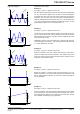
Thefollowingparameterscanbeconguredforatriangularwavefunction:
Value Range Description
I(A), U(A) 0...(Nominal value - (Off)) of U, I A = Amplitude of the signal to be generated
I(Off), U(Off) 0...(Nominal value - (A)) of U, I Off = Offset, based on the foot of the triangular wave
t1 0.1 ms...36000 s RisingedgetimeΔtofthetriangularwavesignal
t2 0.1 ms...36000 s FallingedgetimeΔtofthetriangularwavesignal
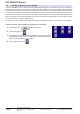
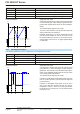
Schematic diagram: Application and result:
Offset
t
A
Amplitude
t1t2
A triangular wave signal for output current (only effective
in current limiting) or output voltage is generated. The
positive and negative slope times can be set indepen-
dently.
The offset shifts the signal on the Y-axis.
The sum of the intervals t1 and t2 gives the cycle time
and its reciprocal is the frequency.
Example: a frequency of 10 Hz is required and would
lead to periodic duration of 100 ms. This 100 ms can
be freely allocated to t1 and t2, e.g. 50 ms:50 ms (isos-
celes triangle) or 99.9 ms:0.1 ms (right-angled triangle
or sawtooth).
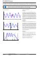
3.9.7 Rectangular function
Thefollowingparameterscanbeconguredforarectangularwavefunction:
Value Range Description
I(A), U(A) 0...(Nominal value - (Off)) von U, I A = Amplitude of the signal to be generated
I(Off), U(Off) 0...(Nominal value - (A)) von U, I Off = Offset, based on the foot of the rectangular wave
t1 0.1 ms...36000 s Time (pulse width) of the upper level (amplitude)
t2 0.1 ms...36000 s Time (pause width) of the lower level (offset)
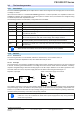
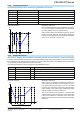
Schematic diagram: Application and result:
Offset
t
A
Amplitude
t1 t2
A rectangular or square wave signal for output current
(only effective in current limiting) or output voltage is
generated.Theintervalst1andt2denehowlongthe
value of the amplitude (pulse) and how long the value
of the offset (pause) are effective.
The offset shifts the signal on the Y-axis.
Intervalst1andt2canbeusedtodeneadutycycle.The
sum of t1 and t2 gives the cycle time and its reciprocal
is the frequency.
Example: a rectangular wave signal of 25 Hz and a
duty cycle of 80% are required. The sum of t1 and t2,
the period, is 1/25 Hz = 40 ms. For a duty cycle of 80%
the pulse time (t1) is 40 ms*0.8 = 32 ms and the pause
time (t2) is 8 ms.