
Instruction manual


Copyright © 2007, 2008 Eagle Tree Systems, LLC
http://www.eagletreesystems.com
Instruction Manual for Spektrum™ and JR™ Data Interface
Document Version 1.1
Thank you for your purchase! This instruction manual will guide you through the installation and operation of your Spektrum™ and JR™
Data Interface (the Interface). Please read the entire manual carefully before proceeding. If, after you read the manual, you have further
questions or problems, see the Support page on http://www.eagletreesystems.com for additional information, or email us at
support@eagletreesystems.com.
IMPORTANT: It is extremely unlikely that the installation of the Interface will affect your model’s radio range or control. But, as always
after making an electronics change to your model, it is very important that you range and function test your model once the Sensor is
installed to ensure that there is no impact on your system. Make sure that your “antenna down” operating range is within the
manufacturer’s specifications. See your Radio owner’s manual for the correct procedure for your equipment. DO NOT OPERATE IF
YOUR MODEL DOESN’T PASS THE ANTENNA DOWN RANGE CHECK.
Packing List
Your package should include the following: The Interface cable, and a printed version of this manual. Please check our support web page
for the electronic version of this manual which may be updated if changes were made after printing.
What the Interface Does
For the first time ever, see and hear how your receiver is performing real time, while you fly! The interface provides support for wireless
telemetry and logging of all the Spektrum™ and JR ™ RF link performance parameters, with “FlightLog” compatible RX’s. Just think,
while you do your range check, get instant feedback on the Seagull LCD display about how your RF link is performing. And best of all,
audible ‘beep’ alarms can be programmed on the Wireless Dashboard display, to alert you in real time when things start to go wrong during
flight! With the programmable beep capability, you keep your eyes on your model, where they should be, knowing that your Receiver is
getting a good signal at all times unless alarms sound. Fly with confidence knowing that your radio link is performing optimally!
The Interface gives you access to the following parameters:
• Receiver Holds – displays a count of the number of Failsafe Holds that have occurred
• Receiver Lost Frames – displays how many frames have been missed during your flight
• Receiver Antenna A, B, Left and Right Fades – displays fade (poor signal) counts of each antenna (up to four). This helps you to
determine which of your antennas needs to be repositioned.
Supported Products
The Interface cable is designed to plug directly into the Data port of all “FlightLog” compatible Spektrum™ and JR™ receivers. It will not
work with any other receiver brand or model! The Interface works with the eLogger V3 (not the eLogger V1 or V2), with all versions
of our “Pro” and “Glide” systems, and with flash upgradeable firmware versions of our Seagull Flight, Car and Boat (and Recorder) products
(units with firmware version “4.xx” or higher). If you have a “3.xx” or lower recorder firmware version, a hardware upgrade is required.
Please see our support web page for more information on hardware upgrades.
Steps to Follow
Installation and use of the Interface should be quite easy and enjoyable if you follow these few steps:
• Read through the manual to understand the warnings, determine the installation and setup sequence, etc.
• Upgrade the Windows Application and Firmware for your Recorder as described in the “Windows Application and Firmware
Update” section below.
• Install and configure the Interface as described below.
Windows Application and Firmware Update
To use the Interface, you must update to Eagle Tree Windows Application version 6.08 or higher. To update, download the latest
application from the support page of our website, located at http://eagletreesystems.com/Support/apps.htm . After downloading and
installing the Application, the firmware of your eLogger or Recorder and Dashboard will need to be updated. To upgrade your firmware,
just choose “Tools, Firmware Control” and click the Update button.
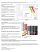
Connecting the Interface Cable to your Receiver
The 3 pin JR style plug on the interface cable is polarized. Simply plug the JR end of the cable into the Data port of your Receiver. NOTE:
there are only two wires on the JR end of the cable, and the color of these two wires is probably different than the “standard” wire colors.