
QCPort System Installation Manual


Intelligent Technologies QCPort System Install Manual
November 2005
MN05001002E For more information visit
www.eatonelectrical.com
Page
23
Using the Sizing Calculation
The following examples use the sizing calculation to determine if the power supply is
placed correctly in the system and if the power supply is large enough for the application.
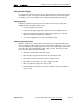
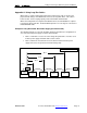
Example 1 End Connected Power Supply
1. Sum up all the currents (QCPort Interconnect system)
=0.1 + 1.1 + 0.3 = 1.5A (too much for Interconnect)
The supply will have to be relocated.
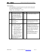
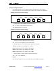
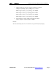
Example 2 End Connected Power Supply
1. Sum up the currents (QCPort Interconnect system)
=0.1 + 0.4 + 0.3 = 0.8 A (OK since 10 feet allows 1.0A)
2. Find the voltages for each node using the equation for Long Run.
SUM {[(L
n
x (0.105)) + (N
t
x (0.005))] x I
n
} <= 4.65V
Device 1 [(20 x (0.105)) + (1 x (0.005))] x 0.1 = 0.21V
Device 2 [(30 x (0.105))+ (2 x (0.005))] x 0.4 = 1.26V
Device 3 [(40 x (0.105)) + (3 x (0.005))] x 0.3 = 1.26V
3. Add each Devices voltage together to find the total voltage.
0.21 + 1.26 + 1.26 = 2.73V (OK)
Results
Since the total voltage does not exceed 4.65V, the system will operate properly.
PS
D2
0.4A
D3
0.3A
T
D1
0.1A
10 foot 10 foot 10 foot 10 foot
T
10 foot
PS
D2
1.1A
D3
0.3A
T
D1
0.1A
1 foot 1 foot 1 foot 1 foot
T
1 foot