
Installation Guide

8/3/11JF
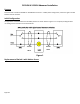
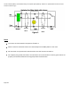
The first switch (SW1) is connected directly to the power (Hot /Neutral). Switch 1 is replaced with the sensor and is
wired as shown in Fig 2.
Figure 2
Notes
The sensor must be located in the position of Switch 1.
Switch 2 must be rewired as shown. The second output of the 3Way Switch is not used.
No connection is required to the second traveler wire that connects to Switch 2.
For simplicity the ground connections are not shown. Care must be taken to ensure ground wires are
properly connected as defined in the original product documentation.
Traveler
Wires
Traveler
Wires