Instruction Booklet IB 70-8698 Effective December 2009 Instruction Manual for the Eaton RTC-100 Automatic Transfer Switch Controller Contents Description 1. 2. 3. 4. 5. Page Introduction. . . . . . . . . . . . . . . . . . . . . . . . . . . . . . . . . . . . . . . . . . . . . . . . . . . . . . . . . . . . . . . . . . . . . . . 2 Hardware Description. . . . . . . . . . . . . . . . . . . . . . . . . . . . . . . . . . . . . . . . . . . . . . . . . . . . . . . . . . . . . . . 5 Operation.. . . . . . . . . .
Instruction Booklet IB 70-8698 Effective December 2009 Section 1: Introduction Caution All possible contingencies that may arise during installation, operation, or maintenance, and all details and variations of this equipment do no purport to be covered by these instructions.
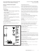
Instruction Manual for the Eaton RTC-100 Automatic Transfer Switch Controller Instruction Booklet IB 70-8698 Effective December 2009 1.3 Product Overview 1.4 Glossary The RTC-100 controller is a comprehensive, multi-function, microprocessor-based ATS controller. Designed to meet the needs of markets worldwide, the RTC-100 controller: With respect to their use within this document and as they relate to transfer switch and controller operation, the following terminology is defined.
Instruction Booklet IB 70-8698 Effective December 2009 1.5 Functions/Features The primary function of RTC-100 controller is to accurately monitor the Utility and Generator power sources and provide the necessary intelligence to operate the ATS in an appropriate and timely manner. In addition, the RTC-100 controller provides status information through on-board and remote indicators. Instruction Manual for the Eaton RTC-100 Automatic Transfer Switch Controller 12.
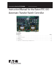
Instruction Manual for the Eaton RTC-100 Automatic Transfer Switch Controller Instruction Booklet IB 70-8698 Effective December 2009 Section 2: Hardware Description 2.4 Input/Output Connectors 2.1 General Located along the bottom of the RTC-100 are connectors J1, J2, and J3. J1 provides board control power and voltage monitoring for both the Utility and Generator sources. J2 and J3 provide load current information that is used for the active load control portion of the RTC-100.
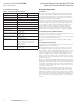
Instruction Manual for the Eaton RTC-100 Automatic Transfer Switch Controller Instruction Booklet IB 70-8698 Effective December 2009 Section 3: Operation 2.7 Specification Summary Table 1. RTC-100 Controller Specifications 3.
Instruction Manual for the Eaton RTC-100 Automatic Transfer Switch Controller Instruction Booklet IB 70-8698 Effective December 2009 Section 4: Programming 4.1.1 Load Control Jumper 4.1 Introduction Aside from the built in Active Load Control relays, the RTC-100 has the ability to extend the loads that it can actively control.
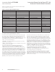
Instruction Booklet IB 70-8698 Effective December 2009 Instruction Manual for the Eaton RTC-100 Automatic Transfer Switch Controller Table 2 is a summary of the Fixed and Jumper-selectable settings that are available in the RTC-100 Table 2.
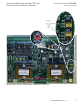
Instruction Manual for the Eaton RTC-100 Automatic Transfer Switch Controller Instruction Booklet IB 70-8698 Effective December 2009 Jumpers shown in the “NO LOAD” test position and “7 DAY” position Figure 3. Generator Test (Plant Exercise) Jumpers and Generator Test Pushbutton. eaton corporation www.eaton.
Instruction Booklet IB 70-8698 Effective December 2009 Instruction Manual for the Eaton RTC-100 Automatic Transfer Switch Controller 4.1.3 Reset Pushbutton If, during normal operation, a transfer (from utility to generator or from generator to utility) does NOT occur when it should, the “CONNECTED” LED’s (WHITE or YELLOW depending on which source should be connected) will flash (see Figure 4).
Instruction Manual for the Eaton RTC-100 Automatic Transfer Switch Controller Active Load Control. 4.1.4 RTC-100 on board Active Load Control 4.1.4.1 Connections There are 2 relays on the RTC-100 that can be used to actively control up to 2 loads while connected to the generator source. The connections are on J8 located on the top of the board. Pins 1 and 2 are the primary load and pins 3 and 4 are the secondary load (see Figure 5). The primary load has priority over the secondary load.
Instruction Booklet IB 70-8698 Effective December 2009 Instruction Manual for the Eaton RTC-100 Automatic Transfer Switch Controller Note that the Ground/ Neutral Side of the Circuits MUST Be Connected to Pins 2 and 4 Figure 6. Typical Connections of Controlled Loads – Non Thermostatically Controlled. 12 eaton corporation www.eaton.
Instruction Manual for the Eaton RTC-100 Automatic Transfer Switch Controller Instruction Booklet IB 70-8698 Effective December 2009 Note that the Ground/Neutral Side of the Circuits MUST Be Connected to Pins 2 and 4 Figure 7. Typical Connections of Controlled Loads – Thermostatically Controlled. eaton corporation www.eaton.
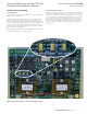
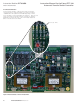
Instruction Booklet IB 70-8698 Effective December 2009 Instruction Manual for the Eaton RTC-100 Automatic Transfer Switch Controller 4.1.4.2 Adjustments – Required for Automatic Load Control There are 4 potentiometers on the RTC-100 that allow the user to program the board with required information about the generator (see Figure 8). Both the RUNNING watts and the STARTING watts are required for the RTC-100 active load control to function properly.
Instruction Manual for the Eaton RTC-100 Automatic Transfer Switch Controller Instruction Booklet IB 70-8698 Effective December 2009 4.1.4.3 Operation While the ATS is connected to the Utility (Primary) source, the J8 contacts on the RTC-100 will close and monitor the loads that are being controlled. The starting KW that is measured when those loads are initiated is kept in memory on the controller.
Instruction Manual for the Eaton RTC-100 Automatic Transfer Switch Controller Instruction Booklet IB 70-8698 Effective December 2009 RTC-100 Active Load Control A Measure Load kW Are controlled load energize signal(s) present? N Y Is this the first measurement with Load on? N Y Is Relay #2 Closed? B Is the Generator powering the Load? N Is Current kW < 80% of Run kW? C Y Y Close relay #1 to allow load #1 to energize Figure 9. Active Load Control Flowchart.
Instruction Manual for the Eaton RTC-100 Automatic Transfer Switch Controller Instruction Booklet IB 70-8698 Effective December 2009 B C Measure Load kW N Is the Generator powering the Load? Y Time 3 Seconds Y Open Relays.
Instruction Manual for the Eaton RTC-100 Automatic Transfer Switch Controller Instruction Booklet IB 70-8698 Effective December 2009 Section 5: Maintenance, Troubleshooting, and Replacement 5.1 Maintenance and Care The RTC-100 is designed to be a self-contained and maintenancefree unit. The printed circuit board is conformally coated at the factory. The RTC-100 is intended for service by factory-trained personnel only. 5.
Instruction Manual for the Eaton RTC-100 Automatic Transfer Switch Controller Instruction Booklet IB 70-8698 Effective December 2009 Notes: eaton corporation www.eaton.
Instruction Booklet IB 70-8698 Instruction Manual for the Eaton RTC-100 Automatic Transfer Switch Controller This instruction booklet is published solely for information purposes and should not be considered all-inclusive. If further information is required, you should consult Eaton. Sale of product shown in this literature is subject to terms and conditions outlined in appropriate Eaton selling policies or other contractual agreement between the parties.