
Instruction manual

2
Instruction Booklet IB 70-8698
Instruction Manual for the Eaton RTC-100
Automatic Transfer Switch Controller
EATON CORPORATION www.eaton.com
Effective December 2009
Section 1: Introduction
CAUTION
ALL POSSIBLE CONTINGENCIES THAT MAY ARISE DURING INSTALLATION,
OPERATION, OR MAINTENANCE, AND ALL DETAILS AND VARIATIONS OF
THIS EQUIPMENT DO NO PURPORT TO BE COVERED BY THESE INSTRUC-
TIONS. IF FURTHER INFORMATION IS DESIRED BY THE PURCHASER
REGARDING A PARTICULAR INSTALLATION, OPERATION, OR MAINTE-
NANCE OF PARTICULAR EQUIPMENT, PLEASE CONTACT AN AUTHORIZED
EATON ELECTRICAL SALES REPRESENTATIVE OR THE INSTALLING CON-
TRACTOR.
1.1 Preliminary Comments and Safety Precautions
This technical document is intended to cover all aspects associated
with the installation, application, operation, and maintenance of the
Automatic Transfer Switch Controller (RTC-100). It is provided as a
guide for authorized and qualified personnel only in the selection and
application of the RTC-100 controller. Please refer to the specific
WARNING and CAUTION in Section 1.1.2 before proceeding. If fur-
ther information is required by the purchaser regarding a particular
installation, application, or maintenance activity, please contact an
authorized Eaton Electrical Sales Representative or the installing
contractor.
1.1.1 Warranty and Liability Information
No warranties, expressed or implied, including warranties of fitness
for a particular purpose of merchantability, or warranties arising from
course of dealing or usage of trade, are made regarding the informa-
tion, recommendations and descriptions contained herein. In no
event will Eaton be responsible to the purchaser or user in contract,
in tort (including negligence), strict liability or otherwise for any spe-
cial, indirect, incidental or consequential damage or loss whatsoever,
including but not limited to damage or loss of use of equipment,
plant or power system, cost of capital, loss of power, additional
expenses in the use of existing power facilities, or claims against
the purchaser or user by its customers resulting from the use of the
information and descriptions contained herein.
1.1.2 Safety Precautions
All safety codes, safety standards, and/or regulations must be
strictly observed in the installation, operation, and maintenance of
this device.
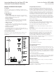
WARNING
THE WARNINGS AND CAUTIONS INCLUDED AS PART OF THE
PROCEDURAL STEPS IN THIS DOCUMENT ARE FOR PERSONNEL SAFETY
AND PROTECTION OF EQUIPMENT FROM DAMAGE. AN EXAMPLE OF A
TYPICAL WARNING LABEL HEADING IS SHOWN ABOVE TO FAMILIARIZE
PERSONNEL WITH THE STYLE OF PRESENTATION. THIS WILL HELP TO
INSURE THAT PERSONNEL ARE ALERT TO WARNINGS, WHICH APPEAR
THROUGHOUT THE DOCUMENT. IN ADDITION, WARNINGS AND
CAUTIONS ARE ALL UPPER CASE AND BOLDFACE.
WARNING
COMPLETELY READ AND UNDERSTAND THE MATERIAL PRESENTED IN
THIS DOCUMENT BEFORE ATTEMPTING INSTALLATION, OPERATION,
OR APPLICATION OF THE EQUIPMENT. IN ADDITION, ONLY QUALIFIED
PERSONS SHOULD BE PERMITTED TO PERFORM ANY WORK ASSOCIATED
WITH THIS EQUIPMENT. ANY WIRING INSTRUCTIONS PRESENTED IN
THIS DOCUMENT MUST BE FOLLOWED PRECISELY. FAILURE TO DO SO
COULD CAUSE PERMANENT EQUIPMENT DAMAGE.
1.2 General Information
Automatic Transfer Switches (ATS) are used to protect critical electri-
cal loads against loss of power. The load’s Utility power source is
backed up by an alternate power source such as a Generator. An
ATS is connected to both the Utility and Generator power sources
and supplies the load with power from one of the two sources. In
the event that power is lost from Utility, the ATS transfers the load
to the Generator power source. Once Utility power is restored, the
load is automatically transferred back to the Utility power source.
An intelligence system initiates the transfer when the Utility power
fails or falls below a preset voltage. An engine start is then initi-
ated by the Generator and the ATS transfers to the Generator power
source when sufficient Generator voltage is available. When the
Utility power is restored, the ATS automatically transfers back to the
Utility and the Generator will shut down after a time delay.
ATSs automatically perform the transfer function, and include three
basic elements:
1. Main contacts to connect and disconnect the load to and from the
power sources.
2. Solenoids to make the transfer of the main contacts from source
to source.
3. Intelligence/supervisory circuits to constantly monitor the condi-
tion of the power sources and thus provide the intelligence nec-
essary for the switch and related circuit operation.
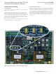
This manual deals with the third basic element of the ATS, the
required intelligence/supervisory circuits. The RTC-100 controller
advances the application of intelligence, supervisory, and program-
ming capabilities for ATS equipment.