
Instruction manual

5
Instruction Booklet IB 70-8698
Instruction Manual for the Eaton RTC-100
Automatic Transfer Switch Controller
EATON CORPORATION www.eaton.com
Effective December 2009
Section 2: Hardware Description
2.1 General
The purpose of this section is to familiarize the reader with the
RTC-100 controller hardware, its nomenclature, and to list the unit’s
specifications.
2.2 LED Indicators
•
Utility Available
The green Utility Available LED illuminates if the utility power
source meets the criteria to be considered “available”. That is,
when it is within its undervoltage range.
•
Generator Available
The red Generator Available LED illuminates if the generator
power source meets the criteria to be considered “available”.
That is, when it is within its undervoltage range.
•
Utility Connected
The White Utility connected LED illuminates when the power
switching device is in a position such that when utility power is
available, it is connected to the load.
•
Generator Connected
The Yellow Generator Connected LED illuminates when the
power switching device is in a position such that when generator
power is available, it is connected to the load.
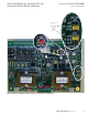
2.3 Programming Jumpers
The RTC-100 controller is programmable via five jumpers on the
PC board. The jumper selections are discussed in Section 4,
Programming.
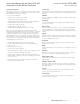
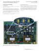
Figure 1. RTC-100 Connectors and Programming Jumpers.
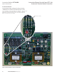
2.4 Input/Output Connectors
Located along the bottom of the RTC-100 are connectors J1, J2,
and J3. J1 provides board control power and voltage monitoring
for both the Utility and Generator sources. J2 and J3 provide load
current information that is used for the active load control portion of
the RTC-100. Along the side of the controller is connector J5. This
connector is currently reserved for future use. Connectors J6, J7,
J8 and J9 are located along the top of the controller. J6 is used for
communication to the RLC-100 load control board. J7 provides a
form C relay with dry contacts that is used for 2 wire engine start
schemes. Connector J8 contains 2 contacts for the active load con-
trol portion of the controller. These contacts are discussed in section
4.1.4. J9 provides connection for the control input and the transfer
switch control outputs.
2.5 Transfer to Generator Input
The RTC-100 has a control input signal that will initiate a transfer
from Utility to Generator. The input requires an external contact clo-
sure to the Transfer to Generator input (J9, pins 1 and 2).
The Control Input “State” definitions are as follows.
Connected - When the input is shorted by an external contact or
connection.
Unconnected - When the input is NOT shorted by an external con-
tact or connection.
The Transfer to Generator Input operations are defined as follows.
When this input (J9, pins 1 and 2) is in the “Connected” state,
the RTC-100 will initiate a transfer from Utility to Generator. The
Generator will be automatically started. After the Generator
becomes available, TDNE will time out before the transfer to
Generator takes place. Re-transfer will occur when the external con-
tact is opened or under a failsafe condition.
2.6 Output Connections
The RTC-100 output connections are divided into two categories:
•
Customer Connections
•
Transfer Operation Connections.
2.6.1 Customer Connections
Load Shed Contacts
There are two sets of load shed contacts for customer use on con-
nector J8, Load Shed Contacts #1 and Load Shed Contacts #2. Both
sets of contacts are closed when the transfer switch is in the Utility
position and both sets are automatically controlled when the transfer
switch is in the Generator position. The output contacts are rated for
5 amps @ 250 VAC. The DC rating is 5 amps @ 30 VDC. See Section
4.1.4 for more information
2.6.2 Transfer Operation Connections
The Utility Close and Gen Close outputs are factory wired to operate
the transfer switch. The relay contacts for each output are rated for
5 amps @ 250 VAC. The DC rating is 5 amps @ 30 VDC.
Utility Close Outputs
This output is used to transfer to Utility. The Utility Close Outputs
are on J9, pins 5 and 6.
Generator Close Outputs
This output is used to transfer to Generator. The Generator Close
Outputs are on J9, pins 3 and 4.