
Manual
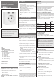

Contents
1 Use
2 Features
3 Functional description
3.1 Testing the transmission range
4 Commissioning
4.1 Establishing wireless connection
4.2 Delete radio link
4.3 Power failure
4.4 Interferences
4.4.1 Double addressing
4.4.2 Faults
4.5 Trouble shooting
5 Technical data
6 Quick reference
Subject to change.
1 Use
Radio frequency receiver for INSTAT+ 868-r (Room
temperature controller with clock) or INSTAT+ 868-
r1 (Room temperature controller without clock).
For switching electrical devices such as:
• Electric radiators
• Electric wall-mounted heating systems
• Electric towel dryers
Caution: Do not plug multiple receivers in a
cascade!
2 Features
• Can be directly inserted into a wall socket outlet
• Switches up to 10 A
• One transmitter can control several receivers
• Self-leaning address tuning through “Learning
Mode” in the transmitter
• One touch button for selecting functions
• Signal lamp indicates faults
• Monitoring of valid radio link
• Acoustic signal in the event of failure
• Emergency operation in case of transmition
faults
3 Functional description
The INSTAT 868-a1S receiver converts the transmis-
sion signals of the INSTAT 868-r… transmitters into
control signals for electrical devices. The devices are
switched via this receiver.
3.1 Testing the transmission range
To determine the radio link range, proceed as follows:
Continuously set 30 °C and 5 °C on the transmitter;
the receiver will switch on and o. If the receiver
stops to switch, the radio link range has been
exceeded.
4 Commissioning
4.1 Establish wireless connection
Note: Products delivered as set are already lin-
ked. For test perform “Testing the radio range”
3.1
To make the receiver work properly, a connection
must be established to the transmitter. Follow the
steps below:
a) On the transmitter, switch to “Learning mode”
(see transmitter operating instructions)
b) On the receiver activate the “Learning mode” as
follows:
Briey press the button, short signal tone, lamp
is blinking.
When the transmitter has been recognised,
short signal tone, signal lamp goes o.
For thermostats without clock: 2 x blinking
For thermostats with clock: 4 x blinking
c) On the transmitter, terminate the “Learning
mode”.
d) For testing the wireless connection just establis-
hed, see 3.1.
Note: Before learning again a transmitter “Deleting
radio links” has to be carried out see 4.2. After that
the connections can be re-learned.
4.2 Deleting a radio link
The conection between transmitter and receiver
will be deleted.
• Press the button for 5 seconds
(there is a short beep, light ashes)
After 5 seconds, a short signal tone. The lamp
expires
• Release button.
4.3 Power failure
In the event of a power failure in the transmitter or in
the receiver, all data will be preserved. When voltage
is available again, normal operation will continue.
4.4 Faults
If a fault occurs, an alarm is triggered and an audible
signal sounds.
4.4.1 Double addressing
2 transmitters transmit with the same address.
A dual audible signal sounds as a warning.
Control lamp blinks – see Table 1.
To cancel the alarm, re-program the transmitter.
4.4.2 Loss of transmission signal
If the transmitter fails to receive an actuating signal
for more than 1 hour, emergency mode will be
triggered.
Once the actuating signal is restored, the emergen-
cy mode will be cancelled automatically.
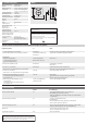
Table 1: Function of the lamp and signal tone
Action Lamp
Signal
tone
No signal of thermostat
without clock **
single
blinking
single
No signal of thermostat
with clock **
double blin-
king
single
Double addressing * no
signicance
double
* No emergency mode:
** Emergency mode:
• Signal tone appears, lamp is blinking
•
Starting o with 30 % energy (3 Min on, 7 Min. o)
Note:
In some rare cases it may not be possible to
establish a permanent radio link between the
radio transmitter and the radio receiver. We
therefore recommend to check the reliability of
operation at the specic location.
For testing the reliability of operation see 3.1
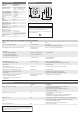
4.5 Trouble shooting
1.
Device will not switch on:
Has wireless connection been established
(refer to 4.1)?
Refer to Table 2, Section 4 onward
2.
It beeps
for general information see 4.4
two transmitter transmit with same address,
see 4.4.1!
No wireless connection, see table 2, Section
6.
3.
Transmitter can not be learned in
Run „delete wireless connection“ see 4.2
4.
Reverse control action
To re-set to normal operation
• Push button briey, short audible signal, cont-
rol lamp blinks
• Push and hold button pushed
after 5 seconds, a short audible signal will
sound, control lamp will blinks slowly
• For normal operation:
Release button when control lamp is OFF
• Audible signal conrms successful setting
468 931 003 935-7
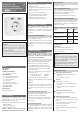
Operating and t
Installation Instructions
Plug In radio freq. receiver
.-a1 S
Caution!
This electronic device, which is looped into the
connection lead, is intended for temperature
control in dry and closed rooms only.
This device conrms to EN 60730, it works
according operating principle 1C