
Full Product Manual


10
Product Support: Eccotemp.com/help-desk Shop Online: Eccotemp.com/products Store Locator: Eccotemp.com/locator
11
Product Support: Eccotemp.com/help-desk Shop Online: Eccotemp.com/products Store Locator: Eccotemp.com/locator
Phone: 866-356-1992 | Email: Support@eccotemp.com Address: 315 - A Industrial RD Summerville, SC 29483 Phone: 866-356-1992 | Email: Support@eccotemp.com Address: 315 - A Industrial RD Summerville, SC 29483
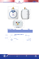
The T/P valve is marked with a maximum pressure, which does not exceed the
maximum working pressure of the water heater (150 PSI).
Install the T /P valve into the threaded opening at the top of the water heater
and orient the discharge tubing so that any discharge from the valve will exit
within 6 inches above, or at any distance below the structural oor, and cannot
contact any live electrical part.
T /P Valve Discharge pipe:
1. Must NOT be smaller in diameter than the outlet diameter of the valve, or have
any reducing couplings.
2. Must NOT be plugged or blocked.
3. Must be made of suitable material for hot water.
4. Must not be over 15 in length.
5. Must not have more than two elbows.
6. Must terminate at an adequate drain.
7. Must not have a shut off valve between relief valve and tank or relief valve and
termination of discharge.
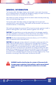
CLOSED SYSTEM THERMAL EXPANSION: Periodic discharge of the T /P relief valve
or failure of the element gasket may be due to thermal expansion in a closed
water supply system. The water utility supply meter may contain a check valve,
backow preventer or water pressure-reducing valve that will create a closed
water system. During the heating cycle of the water heater, the heated water
expands causing pressure inside the water heater to increase. The T /P relief valve
may discharge hot water under these conditions that results in a loss of energy
and a build up of lime on the relief valve seat.
To prevent this from happening, there are two recommendations:
1. Install a diaphragm-type domestic hot water expansion tank (suitable for
potable water) on the cold water supply line. The expansion tank must have a
minimum capacity of 1.5 U.S. gallons for every 50 gallons of stored water.
2. Install a 125-PSI pressure relief valve in the cold water supply line. Make
sure the discharge of this valve is directed to an open drain and protected from
freezing.
Contact your local water utility or plumbing inspector for information on how to
control this situation. Never plug the outlet of the relief valve.