
Full Product Manual


8
Product Support: Eccotemp.com/help-desk Shop Online: Eccotemp.com/products Store Locator: Eccotemp.com/locator
9
Product Support: Eccotemp.com/help-desk Shop Online: Eccotemp.com/products Store Locator: Eccotemp.com/locator
Phone: 866-356-1992 | Email: Support@eccotemp.com Address: 315 - A Industrial RD Summerville, SC 29483 Phone: 866-356-1992 | Email: Support@eccotemp.com Address: 315 - A Industrial RD Summerville, SC 29483
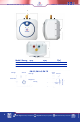
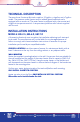
PLUMBING CONNECTIONS
Connect the cold-water inlet pipe to the inlet nipple (marked with a blue ring) and
the hot water outlet pipe to the outlet nipple (marked with a red ring).
IMPORTANT: If Water pipes are copper or bronze, use dielectric connections to
prevent corrosion. Failure to provide dielectric insulation may result in premature
tank or nipple failure and may void your warranty. Ensure that the water heater
is installed in a level position. Install a shut off valve on the cold water side of the
water heater. The valve is for servicing and the valve should be in the open position
when the water heater is in operation. In order to protect the water heater from
heat damage due to soldering, solder a piece of tubing to a threaded UNION tting
before screwing the UNION to the tank.
DO NOT APPLY HEAT DIRECTLY TO INLET OR OUTLET CONNECTIONS.
TEMPERATURE AND PRESSURE RELIEF VALVE:
CAUTION!: Install the Temperature/Pressure Relief Valve supplied with the water
heater!
CAUTION: To reduce the risk of excessive pressures and temperatures in this
water heater, install temperature and pressure protective equipment required
by local codes and no less than a combination temperature and pressure relief
valve certied by a nationally recognized testing laboratory that maintains
periodic inspection of production of listed equipment or materials, as meeting
the requirements for Relief Valves and Automatic Gas Shutoff Devices for Hot
Water Supply Systems, ANSI Z21.22. This valve must be marked with a maximum
set pressure not to exceed the marked maximum working pressure of the water
heater. Install the valve into an opening provided and marked for this purpose in
the water heater, and orient it or provide tubing so that any discharge from the
valve exits only within 6 inches above, or at any distance below, the structural
oor, and does not contact any live electrical part. The discharge opening must
not be blocked or reduced in size under any circumstances.
Install a discharge pipe from the temperature/pressure relief valve terminating
at a sink or drain. DO NOT CAP OR PLUG THE END OF THE DISCHARGE PIPE. THE
DISCHARGE PIPE MUST BE UNOBSTRUCTED AND FULLY SIZED.
A nationally recognized test lab that maintains periodic inspections of the listed
equipment and meets the requirements for relief valves certies the T/P valve and
automatic shut off devices for hot water supply systems ANSI Z21.22.