Power Blower Operator's Manual MODEL PB-260L Serial Number 03001001- 03999999 PB-261L Serial Number 02001001 - 02999999 WARNING DANGER Read rules for safe operation and all instructions carefully. ECHO provides this Operator's Manual which must be read and understood for proper and safe operation.
INTRODUCTION Welcome to the ECHO family. This ECHO product was designed and manufactured to provide long life and on-the-jobdependability. Read and understand this manual. You will find it easy to use and full of helpful operating tips and SAFETY messages. THE OPERATOR'S MANUAL Read and understand this manual before operation. Keep it in a safe place for future reference.
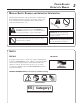
POWER BLOWER OPERATOR'S MANUAL MANUAL SAFETY SYMBOLS AND IMPORTANT INFORMATION Throughout this manual and on the product itself, you will find safety alerts and helpful, information messages preceded by symbols or key words. The following is an explanation of those symbols and key words and what they mean to you. This symbol accompanied by the words WARNING and DANGER calls attention to an act or condition that can lead to serious personal injury to operator and bystanders.
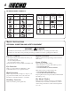
INTERNATIONAL SYMBOLS Symbol form/shape Symbol description/application Symbol form/shape Symbol description/application Read and understand Operator's Manual. Fuel and oil mixture Wear eyes, ears and head protection Finger Severing Symbol form/shape Symbol description/application Wear hand protection. Use two handed. Carburetor adjustment - Low speed mixture Wear slip resistant foot wear. Safety/Alert DO NOT allow flames or sparks near fuel.
POWER BLOWER OPERATOR'S MANUAL EXTENDED OPERATION/EXTREME CONDITIONS Vibration and Cold -It is believed that a condition called Raynaud’s Phenomenon, which affects the fingers of certain individuals, may be brought about by exposure to vibration and cold. Exposure to vibration and cold may cause tingling and burning sensations, followed by loss of color and numbness in the fingers. The following precautions are strongly recommended, because the minimum exposure which might trigger the ailment is unknown.
SAFE OPERATION WARNING DANGER Do not operate this product indoors or in inadequately ventilated areas. Engine exhaust contains poisonous emissions and can cause serious injury or death. • • • • • Review area to be cleared. Look for potential hazards such as stones or metal objects. Spectators and fellow workers must be warned, and children and animals prevented from coming nearer than 15 m (50 ft.) while the blower is in use. Take wind conditions into account: avoid open doors and windows.
POWER BLOWER OPERATOR'S MANUAL EMISSION CONTROL California Tier 2 Model PB-261L EPA Phase 2 Model PB-260L The emission control system for these engines are EM (Engine Modification). An Emission Control Label is located on the engine. (This is an EXAMPLE ONLY, information on label varies by engine FAMILY). IMPORTANT ENGINE INFORMATION ENGINE FAMILY: YEHXS.0254CB DISPLACEMENT: 25.4 CC THIS ENGINE MEETS U.S. EPA PH2 AND 2000 AND LATER CALIFORNIA EMISSION REGULATIONS FOR S.O.R.E.
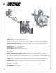
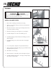
10 13 1 2 9 14 15 11 3 8 7 6 5 4 12 1. 2. 3. 4. 5. 6. 7. 8. 9. 10. 11. 12. 13. 14. 15. SAFETY DECAL - Lists important safety precautions. SPARK PLUG - Provides spark to ignite fuel mixture. SPARK ARRESTOR - CATALYTIC MUFFLER / MUFFLER -The muffler or catalytic muffler controls exhaust noise and emission. The spark arrestor screen prevents hot, glowing particles of carbon from leaving the muffler. Keep exhaust area clear of flammable debris.
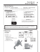
POWER BLOWER OPERATOR'S MANUAL SPECIFICATIONS MOD EL PB -260L PB -261L Length 310 mm (12.62i n.) Wi dth 410 mm (1861 i n.) Hei ght 460 mm (18.1 i n.) Wei ght wi th pi pes Engi ne Type D i splacement 6.6 kg (14.5 lb.) Ai r cooled, two-stroke, si ngle cyli nder gasoli ne engi ne 25.4 cc (1.55 cu. i n.) Bore 34.0 cc (1.34 i n.) 28.0 mm (1.10 i n.
ASSEMBLY A WARNING DANGER Never perform maintenance or assembly procedures with engine running or serious personal injury may result. A INSTALL BLOWER PIPES 1. Remove elbow retaining screw from blower housing. 2. Align grooves in elbow with pegs on blower housing and slide pipe onto housing. 3. Turn elbow clockwise to lock into place and align location holes (A) in elbow and blower housing. 4. Insert elbow retaining screw through holes (A) and tighten. 5.
POWER BLOWER OPERATOR'S MANUAL 11 PRE-OPERATION FUEL Fuel Requirements Gasoline - Use 89 Octane [R +2 M ] (mid grade or higher) gasoline known to be good quality. Gasoline may contain up to 15% MTBE (methyl tertiary-butyl ether). Gasohol containing methyl (wood) alcohol is NOT approved. Two Stroke Oil - A two-stroke engine oil meeting ISO-L-EGD (ISO/CD 13738) and J.A.S.O. FC Standards, must be used. Echo brand Premium 50:1 oil meets these standards.
OPERATION • Provide all operators of this equipment with the Operator's Manual and instructions for safe operation. • Check unit for loose nuts, bolts and screws daily. • Recoil starter: Use short pulls - only 1/2-2/3 of rope length for starting. Do not allow the rope to snap back in. Always hold the unit firmly. • Rotate spring loaded throttle handle downward to a comfortable operating position. STARTING COLD ENGINE A 1. Move throttle lever (A) to START/IDLE DETENT position. 2.
POWER BLOWER OPERATOR'S MANUAL STARTING WARM ENGINE A 1. Move throttle lever (A) to start/idle detent position, pull recoil starter handle (E) 4 (four) times and engine should start. Do not use choke (B). NOTE If engine does not start after 4 pulls, use cold start procedures. B E STOPPING ENGINE A 1. Move throttle lever (A) to idle detent position and allow engine to retun to idle before shutting off engine. 2. Move throttle lever (A) to "STOP" position.
3. Allow the engine to warm up at a fast idle for a few minutes. 4. Use lower speed to blow dry leaves from a lawn or flower bed. 5. Additional speed may be necessary to clean grass and leaves from walks, patios and drives. 6. Higher speed may be necessary to move gravel, dirt, snow, bottles or cans from a driveway, street, parking lot or stadium. NOTE Never use a higher speed setting than necessary to perform a task. Remember, the higher the engine speed, the louder the blower noise.
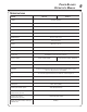
POWER BLOWER OPERATOR'S MANUAL 15 MAINTENANCE INTERVALS COMPONENT/ SYSTEM MAINTENANCE PROCEDURE REQ'D SKILL LE V E L DAILY OR BEFORE U SE EVERY R E FU E L 3 MONTHS OR 90 HOURS 6 MONTHS OR 270 HOURS YEARLY Recommended Echo Dealer Maintenance Procedures Cylinder Exhaust Port Inspect/Clean/Decarbon 3 I/C Do-It-Yourself Maintenance Procedures Air Filter Inspect/Clean/Replace 1 I/C Choke Inspect/Clean 2 I/C Fuel Filter Inspect/Replace 1 Fuel System, Leaks Inspect/Replace 1 I Cooling
AIR FILTER Level 1. Tools required: 25-50 mm (1-2 in.) medium bristle paint brush. Parts required: 90030 REPOWERTM Air and Filter Kit NOTE Clean daily. 1. Close choke (Cold Start Position). This prevents dirt from entering the carburetor throat when the air filter is removed. Brush accumulated dirt from the air cleaner area. 2. Remove the air cleaner cover. Clean and inspect the element for damage. If element is fuel soaked and very dirty, replace. 3.
POWER BLOWER OPERATOR'S MANUAL SPARK PLUG Level 2. Tools required: 3/4 in. Spark Plug deep socket, Feeler gauge (preferably a wire gauge), Parts Required: Spark Plug, NGK BPM-7Y, P/N 99944500071 1. Remove spark plug and check for fouling, worn and rounded center electrode. 2. Clean the plug or replace with a new one. DO NOT sand blast to clean. Remaining sand will damage engine. 3. Adjust spark plug gap by bending outer electrode. 4. Tighten spark plug to 145-155 kg/cm (125-135 in. lb.). 0.65 mm (0.
Cleaning Cylinder Fins 1. Remove engine cover (six screws), pull cover away from engine. Clean cylinder fins to allow cooling air to pass freely. EXHAUST SYSTEM Spark Arrestor Screen Level 2. Tools required: Cross Head Screwdriver, 3 mm Hex Wrench, Soft metal brush, Parts Required: Spark arrestor screen P/N 14586240630, (1ea) Gasket P/N V104000032, V104000350 IMPORTANT Carbon deposits in muffler will cause a drop in engine output and overheating. Spark arrestor screen must be checked periodically. 1.
POWER BLOWER OPERATOR'S MANUAL 19 Cylinder Exhaust Port Level 3. IMPORTANT The cylinder exhaust port must be inspected and cleaned of excess carbon every 3 months or 90 hours of operation in order to maintain this engine within the emissions durability period. ECHO strongly recommends that you return your unit to your ECHO dealer for this important maintenance service. CARBURETOR ADJUSTMENT Level 2. Tools required: Screwdriver, tachometer (Echo P/N 99051130017) Parts required: None.
TROUBLESHOOTING TROUBLESHOOTING CHART Problem C h eck Status Fuel at carburetor No fuel at carburetor Engine runs, but dies or does not accelerate properly Engine does not crank Engine runs, blower doesn't work or i s weak/uneven Remedy Fuel strainer clogged Fuel line clogged Carburetor Clean or replace Clean or replace See your Echo dealer Carburetor See your Echo dealer Fuel Mixture too rich Open choke Clean/replace air filter Adjust carburetor See your Echo dealer No spark Stop switch o
POWER BLOWER OPERATOR'S MANUAL 21 STORAGE WARNING DANGER During operation the muffler - catalytic muffler and surrounding cover become hot. Always keep exhaust area clear of flammable debris during transportation or when storing, otherwise serious property damage or personal injury may result. Long Term Storage (Over 30 Days) Do not store your unit for a prolonged period of time (30 days or longer) without performing protective storage maintenance which includes the following: 1.
NOTES
POWER BLOWER OPERATOR'S MANUAL NOTES 23
SERVICING INFORMATION PARTS Genuine ECHO Parts and ECHO REPOWER™ Parts and Assemblies for your ECHO products are available only from an Authorized ECHO Dealer. When you do need to buy parts always have the Model Number and Serial Number of the unit with you. You can find these numbers on the engine housing. For future reference, write them in the space provided below. Model No. _____________ SN.