Grass Trimmer/Brush Cutter Operator's Manual MODEL SRM - 225U WARNING Read rules for safe operation and instructions carefully. ECHO provides an Operator's Manual and a Safety Manual. Both must be read and understood for proper and safe operation.
Introduction Welcome to the ECHO family. This ECHO product was designed and manufactured to provide long life and on-the-job dependability. Read and understand this manual and the SAFETY MANUAL you found in the same package. You will find both easy to use and full of helpful operating tips and SAFETY messages. the operator's manual Read and understand this manual before operation. Keep it in a safe place for future reference.
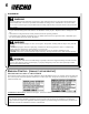
Grass Trimmer/Brush Cutter Operator's Manual 3 Safety manual safety symbols and important information Throughout this manual and on the product itself, you will find safety alerts and helpful, informational messages preceded by symbols or key words. The following is an explanation of those symbols and key words and what they mean to you. Circle and slash symbol DANGER This symbol means the specific action shown is prohibited. Ignoring these prohibitions can result in serious or fatal injury.
Physical Condition Your judgment and physical dexterity may not be good: • if you are tired or sick, • if you are taking medication, • if you have taken alcohol or drugs. Operate unit only if you are physically and mentally well. Eye Protection Wear eye protection that meets ANSI Z87.1 or CE requirements whenever you operate the unit. Hand Protection Wear no-slip, heavy-duty work gloves to improve your grip on the handle. Gloves also reduce the transmission of machine vibration to your hands.
Grass Trimmer/Brush Cutter Operator's Manual Repetitive Stress Injuries 5 It is believed that overusing the muscles and tendons of the fingers, hands, arms, and shoulders may cause soreness, swelling, numbness, weakness, and extreme pain in those areas. Certain repetitive hand activities may put you at a high risk for developing a Repetitive Stress Injury (RSI).
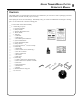
equipment WARNING Use only ECHO approved attachments. Serious injury may result from the use of a non-approved attachment combination. ECHO, INC. will not be responsible for the failure of cutting devices, attachments or accessories which have not been tested and approved by ECHO. Read and comply with all safety instructions listed in this manual and safety manual. • Check unit for loose/missing nuts, bolts, and screws. Tighten and/or replace as needed.
Grass Trimmer/Brush Cutter Operator's Manual 7 Description Locate these safety decals on your unit. Make sure the decals are legible and that you understand and follow the instructions on them. If a decal cannot be read, a new one can be ordered from your ECHO dealer. See PARTS ORDERING instructions for specific information.
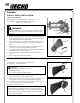
POWER HEAD - Includes the Engine, Clutch, Fuel System, Ignition System and Recoil Starter. THROTTLE TRIGGER LOCKOUT - This lever must be held during starting. Operation of the throttle trigger is prevented unless throttle trigger lockout lever is engaged. 3. STOP SWITCH - "SLIDE SWITCH" mounted on top of the Throttle Trigger Housing. Move switch FORWARD to RUN, BACK to STOP. 4. THROTTLE TRIGGER - Controls engine speed. Spring loaded to return to idle when released.
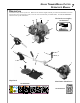
Grass Trimmer/Brush Cutter Operator's Manual 9 Contents The ECHO product you purchased has been factory pre-assembled for your convenience. Due to packaging restrictions, shield installation and other assembly may be necessary. After opening the carton, check for damage. Immediately notify your retailer or ECHO Dealer of damaged or missing parts. Use the contents list to check for missing parts.
Assembly plastic shield installation (Nylon line operation) Tools Required: Torx T27 L-Wrench, Locking Tool B Parts Required: Plastic Debris Shield, Shield Plate, three (3) 5 x 16 mm screws. WARNING The plastic shield is for use with the Nylon Line Head only. Install Metal Shield when using plastic or metal blades, or serious injury may result. 1. 2. 3. 4. 5. 6. Align hole in upper plate (A) with notch in gear housing (B), and insert locking tool to prevent splined shaft from turning.
Grass Trimmer/Brush Cutter Operator's Manual to advance trimmer line See Maintenance Section for nylon line replacement. Tip: To advance trimmer line, tap trimmer head against the ground while the head is turning at normal operating speed. remove nylon line head G Note Do not disassemble nylon line head. 1. 2. 3. Align locking hole in upper plate with notch in edge of gear housing and insert head locking tool (G). Remove line head (J) by turning it clockwise until head is completely off of shaft.
d. Remove three screws holding shield plate and plastic shield (F) to gear housing. e. Retain line head, upper fixing plate, shield plate, and plastic shield for conversion back to nylon line head operation. 2. B Align hole in upper plate (A) with notch in gear housing (B), and insert locking tool to prevent splined shaft from turning. Arrow on gear housing flange points to notch location. 3. Remove split pin (C), L.H. blade nut (D), lower plate (E), and upper plate (A) from PTO shaft (F).
Grass Trimmer/Brush Cutter Operator's Manual u-handle installation Tools Required: 17 & 19 mm wrench, Torx T27 L-Wrench, Parts Required: U-Handle, Clamp w/screws, 8 mm x 55 mm hex bolt, 8 mm flat washer 1. Install upper U-Handle and bracket on lower bracket with one (1) 8mm x 55mm bolt (A) and (1) large circular washer. Do not tighten bolt securely until final adjustments are completed. 2. Loosen upper (2) U-handle clamp screws (B), and position Uhandle as shown. 3.
5. Secure ignition leads against engine housing with clips (H,I). 6. Install air filter and cover. H I H balance and adjust unit 1. Loosen harness clamp screw. 2. Put on harness and attach unit to harness. 3. Slide harness clamp up (A) or down until unit balances with head approximately 50-75 mm (2 -3 in.) from the ground. 4. Tighten harness clamp screw. 5. Loosen upper U-Handle clamp screws (B), and position U-Handle for comfortable operation. 6.
Grass Trimmer/Brush Cutter Operator's Manual 15 Operation WARNING Moving parts can amputate fingers or cause severe injuries. Keep hands, clothing and loose objects away from all openings. Always stop engine, disconnect spark plug, and make sure all moving parts have come to a complete stop before removing obstructions, clearing debris, or servicing unit. WARNING Engine exhaust IS HOT, and contains Carbon Monoxide (CO), a poison gas. Breathing CO can cause unconsciousness, serious injury, or death.
Plastic/Nylon Grass/Weed Blades may be used where ever the nylon line head is used. DO NOT use this blade for heavy weeds or brush! 8 Tooth Weed/Grass Blade (P/N 69600120331) is designed for grass, garden debris and thick weeds. DO NOT use this blade for brush or heavy woody growth, 19 mm (3/4 in.) diameter or larger. 80 Tooth Brush Blade (P/N 69500120331) is designed for cutting brush and woody growth up to 13 mm (1/2 in.) diameter.
Grass Trimmer/Brush Cutter Operator's Manual 17 fuel NOTICE: Use of unmixed, improperly mixed, or fuel older than 90 days, (stale fuel), may cause hard starting, poor performance, or severe engine damage and void the product warranty. Read and follow instructions in the Storage section of this manual. WARNING Alternative fuels, such as E-15 (15% ethanol), E-85 (85% ethanol) or any fuels not meeting ECHO requirements are NOT approved for use in ECHO 2-stroke gasoline engines.
Mixing Instructions 1. Fill an approved fuel container with half of the required amount of gasoline. 2. Add the proper amount of 2-stroke oil to gasoline. 3. Close container and shake to mix oil with gasoline. 4. Add remaining gasoline, close fuel container, and remix. IMPORTANT Spilled fuel is a leading cause of hydrocarbon emissions. Some states may require the use of automatic fuel shut-off containers to reduce fuel spillage. After use • DO NOT store a unit with fuel in its tank.
Grass Trimmer/Brush Cutter Operator's Manual starting cold engine WARNING The attachment will operate immediately when the engine starts and could result in loss of control and possible serious injury. Keep movable parts of the attachment off the ground and away from objects that could become entangled or thrown. 1. Stop Switch Move stop switch button (A) forward away from the STOP position. 2. Choke Move choke lever (B) to Cold Start Position ( 3. A ).
starting warm engine The starting procedure is the same as Cold Start except DO NOT close the choke, and do not hold throttle trigger fully depressed. WARNING The attachment should not move at idle, otherwise serious personal injury may result. NOTE If attachment moves, readjust carburetor according to “Carburetor Adjustment” instructions in this manual or see your ECHO Dealer. 1. Stop Switch Move stop switch button (A) forward away from the STOP position. 2.
Grass Trimmer/Brush Cutter Operator's Manual 21 stopping engine 1. 2. Throttle Release throttle and allow engine to return to idle before shutting off engine. A Stop Switch Move stop switch button (A) backward to STOP position. WARNING If engine does not stop when stop switch is moved to STOP position, close choke - COLD START position - to stall engine. Have your ECHO dealer repair stop switch before using trimmer again.
maintenance intervals COMPONENT/ SYSTEM MAINTENANCE PROCEDURE REQ'D SKILL LEVEL DAILY OR BEFORE USE EVERY REFUEL 3 MONTHS OR 90 HOURS YEARLY 600 HOURS Air Filter Inspect/Clean 1 I/C* Choke Shutter Inspect/Clean 1 I/C Fuel Filter Inspect/Replace 1 I* I/R* Fuel Cap Gasket Inspect/Replace 1 I * R* Fuel System Inspect/Replace 1 Spark Plug Inspect/Clean 1 Cooling System Inspect/Clean 2 Muffler Spark Arrestor Inspect/Clean/Replace 2 I/C/R* Cylinder Exhaust Port Inspect/Cl
Grass Trimmer/Brush Cutter Operator's Manual air filter Level 1. Tools required: 25 - 50 mm (1 - 2 in.) Cleaning Brush Parts required: REPOWERTM AIR & FUEL FILTER KIT. 1. Close choke (Cold Start Position [ ]). This prevents dirt from entering the carburetor throat when the air filter is removed. Brush accumulated dirt from air cleaner area. 2. Remove air filter cover. Brush dirt from inside cover. 3. Remove air filter and lightly brush debris from filter.
spark plug Level 2. Tools required: T-Wrench, feeler gauge, soft metal brush Parts Required: REPOWERTM Tune-Up Kit IMPORTANT Use only NGK BPM-8Y spark plug (BPMR-8Y in Canada) otherwise severe engine damage may occur. 1. Remove spark plug and check for fouling, worn and rounded center electrode. 2. Clean the plug or replace with a new one. DO NOT sand blast to clean. Remaining sand will damage engine. 3. Adjust spark plug gap by bending outer electrode. 4.
Grass Trimmer/Brush Cutter Operator's Manual 1. Remove spark plug lead. 2. Remove air cleaner cover (A). 3. Remove 2 engine cover screws and engine cover (B). (1 machine screw - handle side) (1 tapping screw - starter side) IMPORTANT DO NOT use a metal scraper to remove dirt from the cylinder fins. 4. Use brush to remove dirt from the cylinder fins. 5. Remove ignition wires from clip for cleaning. 6. Remove grass and leaves from the grid between the recoil starter and fuel tank. 7.
1. Remove engine cover screws (2) and engine cover (B). 2. Place piston at Top Dead Center (TDC) to prevent carbon/dirt from entering cylinder. 3. Remove spark arrestor screen cover (C), gaskets (D), (E), and screen (F), from muffler body. E Clean carbon deposits from muffler components. D 4. F C NOTE When cleaning carbon deposit, be careful not to damage the catalytic element inside muffler. 5. Replace screen if it is cracked, plugged, or has holes burned through. 6.
Grass Trimmer/Brush Cutter Operator's Manual carburetor adjustment Engine Break-In New engines must be operated a minimum duration of two tanks of fuel break-in before carburetor adjustments can be made. During the breakin period your engine performance will increase and exhaust emissions will stabilize. Idle speed can be adjusted as required.
lubrication Level 1. Tools Required: 13mm Open End Wrench, T27 Torx L-Wrench, Clean Rag, Grease Gun Parts Required: POWER BLENDXTM 8 oz. (P/N 91014) or Lithium Base Grease. Gear Housing 1. Clean all loose debris from gear box. 2. Remove plug (A) and check level of grease. 3. Add grease if necessary. DO NOT over-fill. A A Drive Shaft 1. Loosen two (2) screws (B) and remove center locating screw (C). Pull gear box and shield from drive shaft housing. 2.
Grass Trimmer/Brush Cutter Operator's Manual nylon line replacement 1. Hold drum securely. Push spool in, and turn clockwise until locking peg clicks. 2. Pull spool out of drum. Clear any remaining line or debris from spool and drum. B A 3. Align pegs on inner drive (A) with grooves in spool (B), and install spool onto drum. Do not push down on spool. Turn spool counter clockwise until locking peg clicks into hole in spool (C). C 4. Align arrows on spool with marks on drum. 5.
6. Hold drum securely, and turn spool clockwise to wind line onto spool. 7. Cut remaining line loop to separate into two pieces.
Grass Trimmer/Brush Cutter Operator's Manual sharpening metal blades Three styles of metal blades are approved for use on the ECHO Brush Cutter. The 8-tooth blade can be sharpened during normal maintenance. The clearing blade and 80 tooth blade require professional service. Before sharpening, CLOSELY inspect blade for cracks (look at the bottom of each tooth and the center mounting hole closely), missing teeth and bending. If ANY of these problems are discovered, replace the blade.
Troubleshooting ENGINE PROBLEM TROUBLESHOOTING CHART Problem C h eck Fuel at carburetor Fuel at cylinder Engine cranks starts hard/ doesn't start Engine runs, but dies or does not accelerate properly Engine does not crank Status C au se No fuel at carburetor Fuel strainer clogged Fuel line clogged Carburetor Remedy Clean or replace Clean or replace See your Echo dealer No fuel at cylinder Carburetor See your Echo dealer Muffler wet with fuel Fuel Mixture too rich Open choke Clean/replace ai
Grass Trimmer/Brush Cutter Operator's Manual 33 Storage warning During operation the muffler or catalytic muffler and surrounding cover become hot. Always keep exhaust area clear of flammable debris during transportation or when storing, otherwise serious property damage or personal injury may result. Long Term Storage (over 30 days) Do not store your unit for a prolonged period of time (30 days or longer) without performing protective storage maintenance which includes the following: 1.
Specifications MODEL ���������������������������������������������������� SRM-225U Length ������������������������������������������������������� 1793 mm (70.6 in.) Width �������������������������������������������������������� 700 mm (27.5 in.) Height ������������������������������������������������������� 510 mm (20.1 in.) Weight (dry) w/Cutter Head ������������������������������ 5.98 kg (13.2 lb.
Grass Trimmer/Brush Cutter Operator's Manual Warranty Statements ECHO LIMITED WARRANTY STATEMENT FOR PRODUCT SOLD IN USA AND CANADA BEGINNING 01/01/2010 ECHO'S RESPONSIBILITY ECHO Incorporated’s Limited Warranty, provides to the original purchaser that this ECHO product is free from defects in material and workmanship.
PURCHASED REPAIR PARTS, SHORT BLOCKS AND ACCESSORIES • 90-day residential, or non-income producing warranty • 30-day commercial, institutional, agricultural, industrial, income producing, or rental application warranty ATTENTION TWO-STROKE ENGINE POWER PRODUCT OWNERS This ECHO two-stroke engine power product is a quality-engineered unit which has been manufactured to exact tolerances to provide superior performance.
Grass Trimmer/Brush Cutter Operator's Manual ECHO INCORPORATED EMISSION CONTROL WARRANTY STATEMENT FOR ECHO AND SHINDAIWA BRANDS The Environmental Protection Agency (EPA) and the California Air Resources Board (C.A.R.B.) and ECHO Incorporated (ECHO Inc.) are pleased to explain the emission control system warranty on your 2010 and later equipment/small off-road engine (SORE). New equipment/SORE must be designed, built and equipped to meet stringent EPA and C.A.R.B. anti-smog standards. ECHO Inc.
notes
Grass Trimmer/Brush Cutter Operator's Manual notes 39
Servicing Information parts/serial number Genuine ECHO Parts and ECHO REPOWER™ Parts and Assemblies for your ECHO products are available only from an Authorized ECHO Dealer. When you do need to buy parts always have the Model Number, Type and Serial Number of the unit with you. You can find these numbers on the engine housing. For future reference, write them in the space provided below. Model No. _________________SN.